
Vehicle headlight device

一种头灯、车辆的技术,应用在车头灯、照明装置、信号装置等方向,能够解决变暗、不能高水平的分辨率设定光分布图案的暗区域等问题

Active Publication Date: 2017-03-01
TOYOTA JIDOSHA KK
View PDF11 Cites 9 Cited by
  • Summary
  • Abstract
  • Description
  • Claims
  • Application Information

AI Technical Summary

Problems solved by technology

[0005] In the vehicle headlight devices disclosed in JP 2015-016773 A and JP 2009-227088 A, it is not possible to set the Dark areas of the light distribution pattern
Therefore, there arises a problem that even areas that could otherwise be illuminated with high beams are included in dark areas
In other words, the problem arises that even areas that could otherwise be illuminated with high beams are affected by switching off the LEDs or being shaded with movable shutters and become darker

Method used


Image

  • Vehicle headlight device
  • Vehicle headlight device
  • Vehicle headlight device

Examples


no. 1 approach

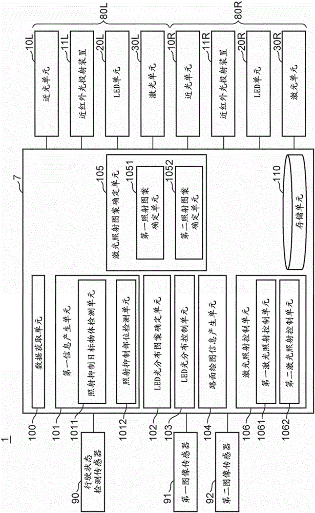
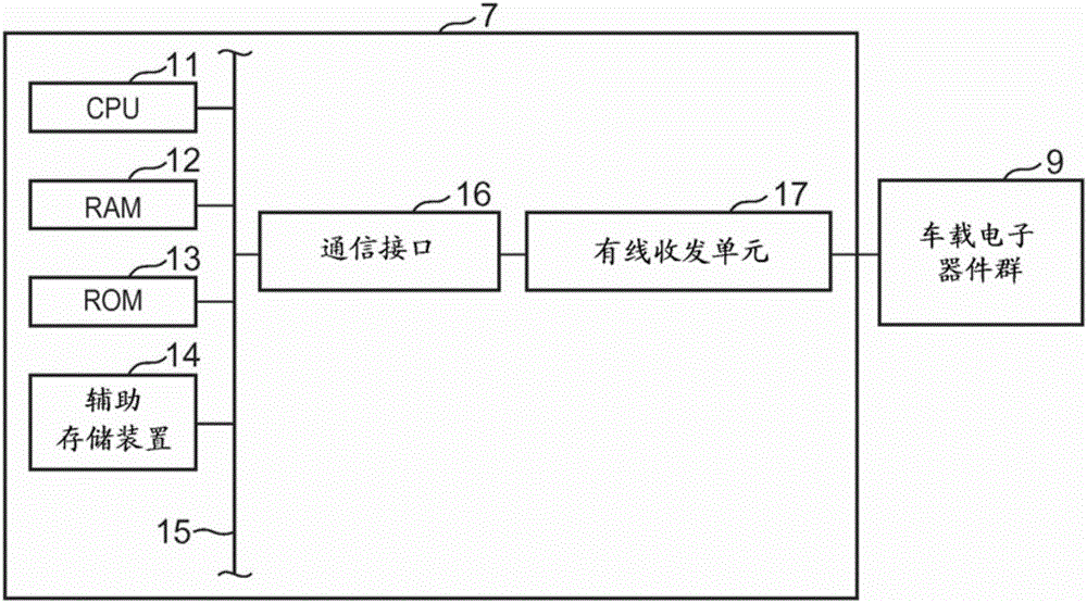
[0056] Hereinafter, a first embodiment of the present invention will be described. figure 1 is a diagram showing a configuration diagram of the vehicle headlight device 1 according to the first embodiment of the present invention. figure 2 is a diagram showing an example of the hardware configuration of the control device. figure 2 A group of in-vehicle electronic components 9 is schematically shown in FIG. 2 , and the group of in-vehicle electronic components 9 is associated with the hardware structure of the information recording ECU 7 .

[0057] The vehicle headlight device 1 is mounted on a vehicle. The vehicle on which the vehicle headlight device 1 is mounted will be referred to as "own vehicle".

[0058] The vehicle headlight device 1 includes a control device 7 , a right headlight 80R and a left headlight 80L, a running state detection sensor 90 , a first image sensor 91 , and a second image sensor 92 .

[0059] like figure 2 As shown in , the control device 7 i...

no. 2 approach

[0155] Figure 15 is a diagram showing a configuration diagram of a vehicle headlight device 1A according to the second embodiment of the present invention.

[0156] The vehicle headlight device 1A is different from the vehicle headlight device 1 according to the first embodiment described above in that, in the vehicle headlight device 1A, the control device 7 is replaced with a control device 7A. The control device 7A is different from the control device 7 according to the first embodiment described above in that the first information generating unit 101 is replaced with a first information generating unit 101A, and the LED light distribution pattern is replaced with an LED light distribution pattern determination unit 102A The determination unit 102 replaces the laser irradiation pattern determination unit 105 with a laser irradiation pattern determination unit 105A, replaces the laser irradiation control unit 106 with a laser irradiation control unit 106A, and adds a second...


PUM


Abstract

A vehicle headlight device includes: a sensor acquiring information on an object in front of a host vehicle; a first lighting; a second lighting including a laser light, a movable mirror element reflecting the laser light, an actuator driving the movable mirror element; a lighting light distribution pattern control unit that controls a light distribution pattern formed by the first lighting such that an irradiation suppressed site where the irradiation by the first lighting is reduced is included in a dark region where the irradiation by the first lighting is reduced, a laser distribution pattern setting unit used for setting a laser distribution pattern and performing laser irradiation in a region not including the irradiation suppressed site and included in the dark region, and a laser distribution pattern control unit that controls the actuator such that the laser light is reflected in the laser light distribution pattern.

Description

technical field [0001] The present invention relates to a vehicle headlight device. Background technique [0002] There is known a vehicle headlight device that includes a laser light source, a movable mirror element, and an actuator, and which forms various light distribution patterns (for example, refer to Japanese Patent Application Laid-Open No. .2015-38885 (JP 2015-38885 A)). [0003] In addition, there is known a vehicle headlight device that provides illumination to the front of the host vehicle by combining respective LED irradiable areas of a plurality of light emitting diodes (LEDs). In this known vehicle headlight device, in a case where a vehicle in front of the own vehicle is detected (an example of illuminating a suppression target object), some of the plurality of LEDs are turned off or dimmed so as to be incompatible with the preceding vehicle The corresponding area is included in the dark area (area not irradiated with the high beam) of the light distribut...

Claims


Application Information

Patent Timeline
Patent Type & Authority Applications(China)
IPC IPC(8): F21S8/10F21V14/04F21Y115/10F21W101/10
CPCF21S41/675F21S41/60B60Q1/143B60Q2300/054B60Q2300/056B60Q2300/42B60Q2300/45F21V14/04B60Q2400/50F21Y2113/00B60Q2300/41F21Y2103/10F21S41/143F21S41/255F21S41/663F21S41/16F21S41/13F21S41/18F21S41/686F21S41/176F21W2102/145B60Q1/085F21S41/151F21W2103/60B60Q2300/32
Inventor 中岛和彦泽田友成
Owner TOYOTA JIDOSHA KK
Learn More