Electronic component mounting device and electronic component mounting method

A technology for electronic component installation and electronic components, which is applied in the direction of electrical components, electrical components, etc., can solve the problems of less quantity and lower productivity of electronic component installation devices, and achieve the effect of suppressing the reduction of productivity and avoiding interference

Active Publication Date: 2021-04-20
JUKI CORP
View PDF2 Cites 0 Cited by
  • Summary
  • Abstract
  • Description
  • Claims
  • Application Information

AI Technical Summary

Problems solved by technology

As a result, the number of electronic components that can be transported in one transport operation of the mounting head unit from the electronic component supply device to the substrate decreases, resulting in a reduction in the productivity of the electronic component mounting device.

Method used


Image

  • Electronic component mounting device and electronic component mounting method
  • Electronic component mounting device and electronic component mounting method
  • Electronic component mounting device and electronic component mounting method

Examples


no. 1 Embodiment approach >

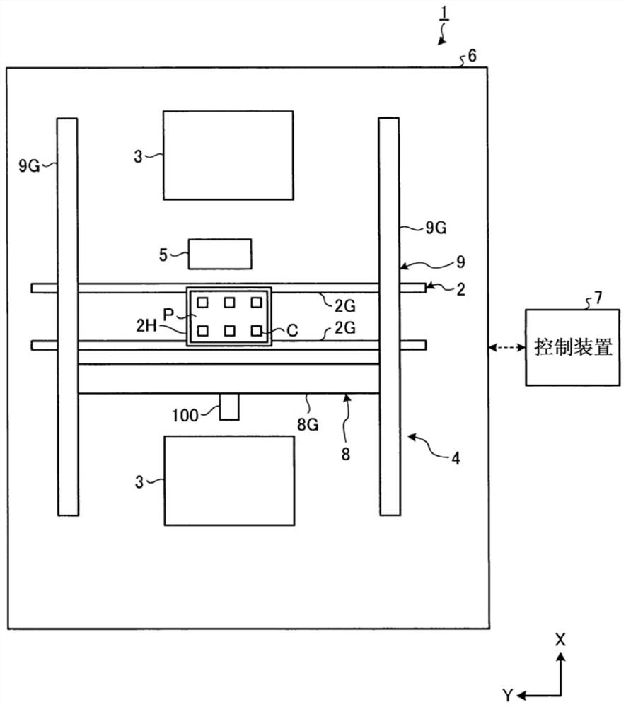
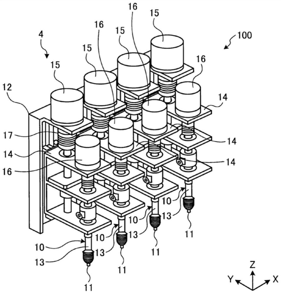
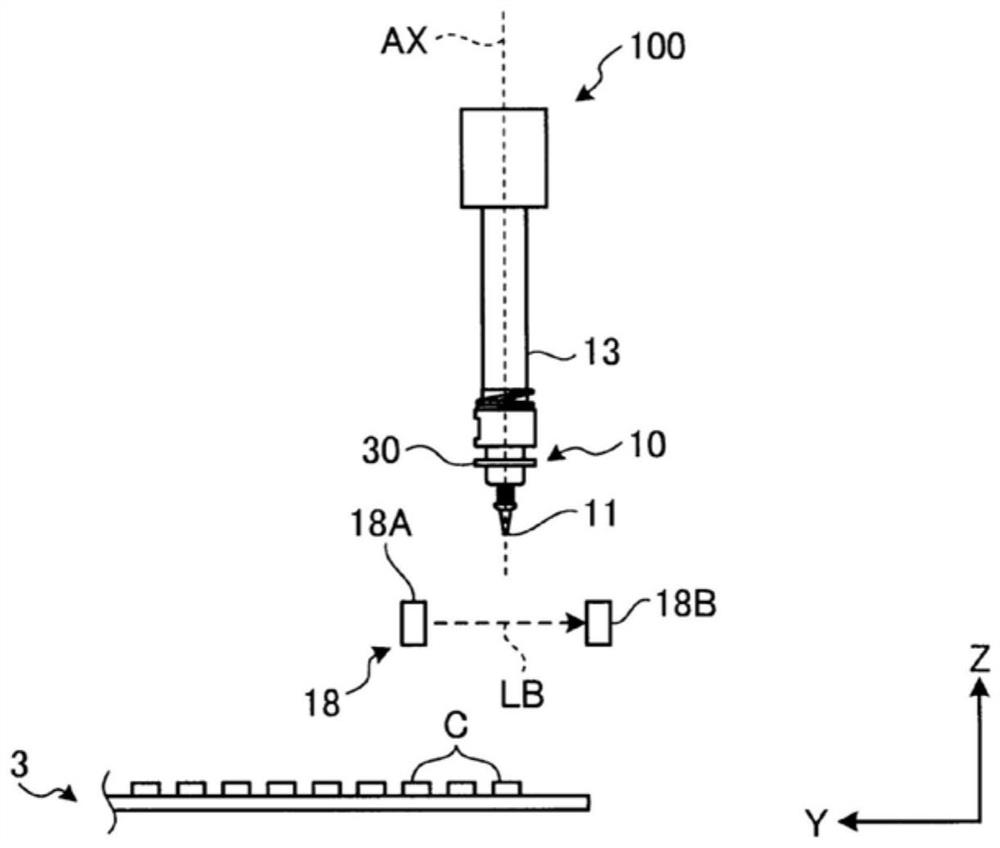
[0085] The first embodiment will be described. figure 1 It is a schematic diagram which shows an example of the electronic component mounting apparatus 1 which concerns on this embodiment. figure 2 It is a perspective view schematically showing an example of the mounting head unit 100 included in the electronic component mounting apparatus 1 according to this embodiment. image 3 It is a side view which shows an example of the mounting head unit 100 which concerns on this embodiment.

[0086] The electronic component mounting apparatus 1 mounts the electronic component C on the board|substrate P. As shown in FIG. The electronic component mounting device 1 is also referred to as a surface mount device 1 or a mounter 1 . The electronic component C may be a lead type electronic component having leads (plug-in type electronic component), or may be a chip type electronic component not having leads (mounted type electronic component). The lead type electronic component is mounte...


PUM


Abstract

The present invention provides an electronic component mounting apparatus capable of transporting as many electronic components as possible while avoiding interference between electronic components, and suppressing a decrease in productivity. An electronic component mounting apparatus includes: a mounting head unit having a plurality of mounting heads; a movement system that moves a suction nozzle of the mounting head; a component dimension data acquisition unit that acquires component dimension data; a mounting head dimension data acquisition unit that acquires Mounting head dimensional data; and a mounting head control unit that outputs a first control signal based on the component dimensional data and the mounting head dimensional data so that the first electronic component supported by the supporting surface of the electronic component supply device is carried out through the first mounting. After the operation of detaching the head from the support surface, an operation of detaching the second electronic component, which is supported by the support surface and has a larger external dimension than the first electronic component, from the support surface by the second mounting head is performed.

Description

technical field [0001] The present invention relates to an electronic component mounting device and an electronic component mounting method. Background technique [0002] The electronic component mounting apparatus mounts electronic components on a board using a head unit having a plurality of heads. A plurality of mounting heads are arranged in a predetermined direction (see Patent Documents 1 and 2). [0003] Patent Document 1: Japanese Patent Application Laid-Open No. 10-322096 [0004] Patent Document 2: Japanese Patent Laid-Open No. 2000-165093 [0005] In order to improve the productivity of the electronic component mounting apparatus, it is effective to collectively hold a plurality of electronic components supplied from the electronic component supply apparatus by a plurality of mounting heads, transport them to a substrate, and mount them. However, depending on the external dimensions of the electronic components or the size of the mounting heads, if an attempt i...

Claims


Application Information

Patent Timeline
Patent Type & Authority Patents(China)
IPC IPC(8): H05K13/04
CPCH05K13/0408H05K13/043H05K13/0478
Inventor 桥本骏己真田侑典樱井茉莉子野尻信明藤田高史
Owner JUKI CORP
Why Eureka
Try Eureka