Oil spraying ring brazing positioning device of turbojet engine

A turbojet engine and positioning device technology, which is applied in auxiliary devices, welding equipment, metal processing equipment, etc., can solve problems such as large roundness and dimensional tolerances, failure to meet design requirements, and falling off of paste solder, etc. The effect of small size, increased adjustment flexibility, and small mass

Active Publication Date: 2017-03-22
BEIJING POWER MACHINERY INST
View PDF5 Cites 5 Cited by
  • Summary
  • Abstract
  • Description
  • Claims
  • Application Information

AI Technical Summary

Problems solved by technology

[0004] 1. In order to ensure the position of each position, the size of the step hole of the chassis and the inner hole of the limit plate are designed precisely, and the diameter is only 0.02-0.04mm larger than the outer surface of each seat. When assembling before brazing, the large end of each seat Placed in the step hole of the chassis, after the oil pipe is installed, because the oil pipe is bent from sheet metal, the roundness and dimensional tolerances are relatively large, the round pipe will generate radial force on each seat, causing each seat to be skewed to a certain extent, within the assembly limit Difficulty in bit disk
[0005] 2. The brazing of the product is pre-set at the interface with cream solder. During the brazing process, it is inevitable that the cream solder will fall off. The tooling is stuck and difficult to disassemble
[0006] 3. The fuel injection ring after brazing becomes a whole. Since the design size of each hole of the tooling is relatively precise and the position is high, it is difficult to disassemble the product after brazing. Generally, it needs to be disassembled by knocking with a leather hammer, which is prone to deformation. As a result, the shape and position tolerances cannot meet the design requirements

Method used


Image

  • Oil spraying ring brazing positioning device of turbojet engine
  • Oil spraying ring brazing positioning device of turbojet engine
  • Oil spraying ring brazing positioning device of turbojet engine

Examples


Embodiment Construction

[0031] The present invention will be described in detail below with reference to the accompanying drawings and examples.

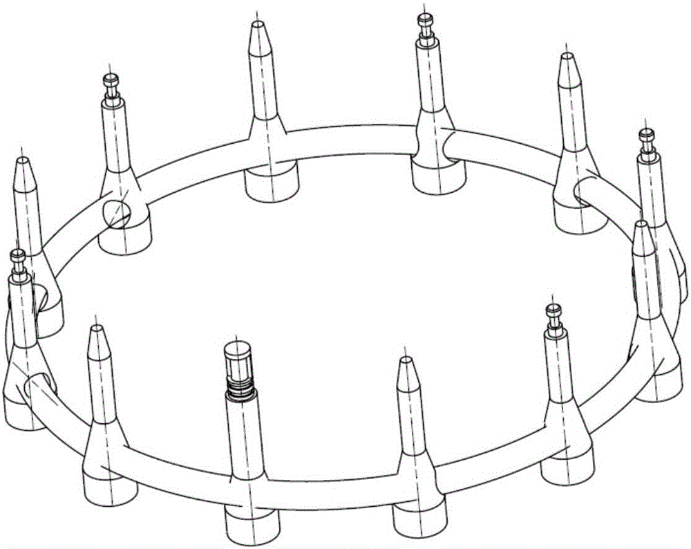
[0032] Such as Figure 5 — Figure 7 As shown, the present invention provides a fuel injection ring brazing positioning device of a turbojet engine, comprising a base 1, an inner positioning ring 2 and 6 outer positioning blocks 3;

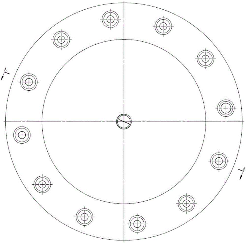
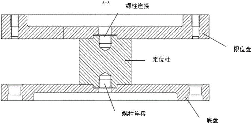
[0033] Such as Figure 8 As shown, the base 1 includes a circular base plate and 6 identical arc-shaped blocks, the 6 arc-shaped blocks are fixedly connected to the base plate, and are evenly distributed on the circumference of the base plate, and threaded holes are provided between adjacent two arc-shaped blocks;

[0034] The inner positioning ring 2 is a 12-sided annular structure, and a semicircular hole is processed at the angle between every two adjacent sides on the outer side of the annular structure. There are 12 semicircular holes in total, and six groups are evenly distributed outside the annular structure. Thread...


PUM


Abstract

The invention discloses an oil spraying ring brazing positioning device of a turbojet engine. The device comprises a base, an inner positioning ring and six outer positioning blocks; the base is a circular plate; six thread holes are uniformly distributed in the base; the inner positioning ring is a twelve-edge annular structure; semicircular holes are machined in included angles of every two adjacent edges of the outer side of the inner positioning ring; six sets of thread holes are uniformly distributed in the outer side of the inner positioning ring; all the sets of thread holes are formed in the middle positions of the edges thereof; six through holes corresponding to the thread holes of the base are uniformly distributed on the end surface of the inner positioning ring; the six outer positioning blocks are spliced as a twelve-edge annular structure; thread through holes are machined in two ends of each outer positioning block; the thread through holes of the outer positioning blocks are corresponding to the thread holes of the inner positioning ring; semicircular holes are respectively machined in included angles of two adjacent edges of the inner sides of all the outer positioning blocks; and the semicircular holes on the inner sides of the six outer positioning blocks and the semicircular holes on the outer side of the inner positioning ring form round holes. The device can reduce the assembly difficulty and improve the production efficiency.

Description

technical field [0001] The invention relates to the technical field of turbojet engine parts manufacturing, in particular to a brazing positioning device for a fuel injection ring of a turbojet engine. Background technique [0002] The fuel injection ring is an important part of the turbojet engine. For the structure of the fuel injection ring, see figure 1 shown. It consists of positioning seat (5 pcs), seat (6 pcs), oil inlet seat (1 pc) and oil pipe (1 pc). The oil inlet pipe and each seat are connected by brazing. At present, the common brazing tooling forms in production are as follows: figure 2 — Figure 4 shown. The existing brazing tooling includes three parts: chassis, positioning column, and limiting plate, wherein the chassis / positioning column, positioning column / limiting plate are connected by studs. There are 12 stepped holes on the chassis for fixing the outer circle and end face of the large end of each seat, and 12 holes on the limit plate are used fo...

Claims


Application Information

Patent Timeline
IPC IPC(8): B23K3/08
CPCB23K3/087
Inventor 蔺晓超张群马瑞孟祥春石祥虎
Owner BEIJING POWER MACHINERY INST
Why Eureka
Try Eureka