
A cage stopper

A technology of vehicle arrester and cage, which is applied to lifting equipment, transportation and packaging in mines. It can solve the problems of vehicles jumping out of the cage, materials or equipment slipping, and jumping out of the cage, so as to achieve the effect of improving safety and good effect

Active Publication Date: 2018-09-21
HUAINAN MINING IND GRP
View PDF4 Cites 0 Cited by
  • Summary
  • Abstract
  • Description
  • Claims
  • Application Information

AI Technical Summary

Problems solved by technology

[0003] Because the wedge-shaped boss in the cage is worn by the wheel due to long-term use, its inclination and height change, once the cage shakes, stops or other abnormal conditions occur during operation, the wheel cannot be effectively blocked by the wedge-shaped boss and the sliding car stopper , the vehicle may jump out of the cage, and the materials or equipment on the vehicle may also slide down and jump out of the cage with the movement of the vehicle

Method used


Image

  • A cage stopper
  • A cage stopper
  • A cage stopper

Examples


Embodiment Construction

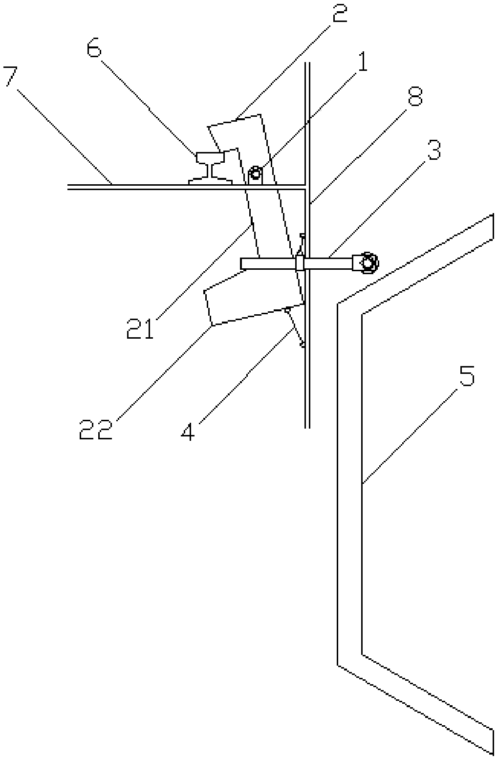
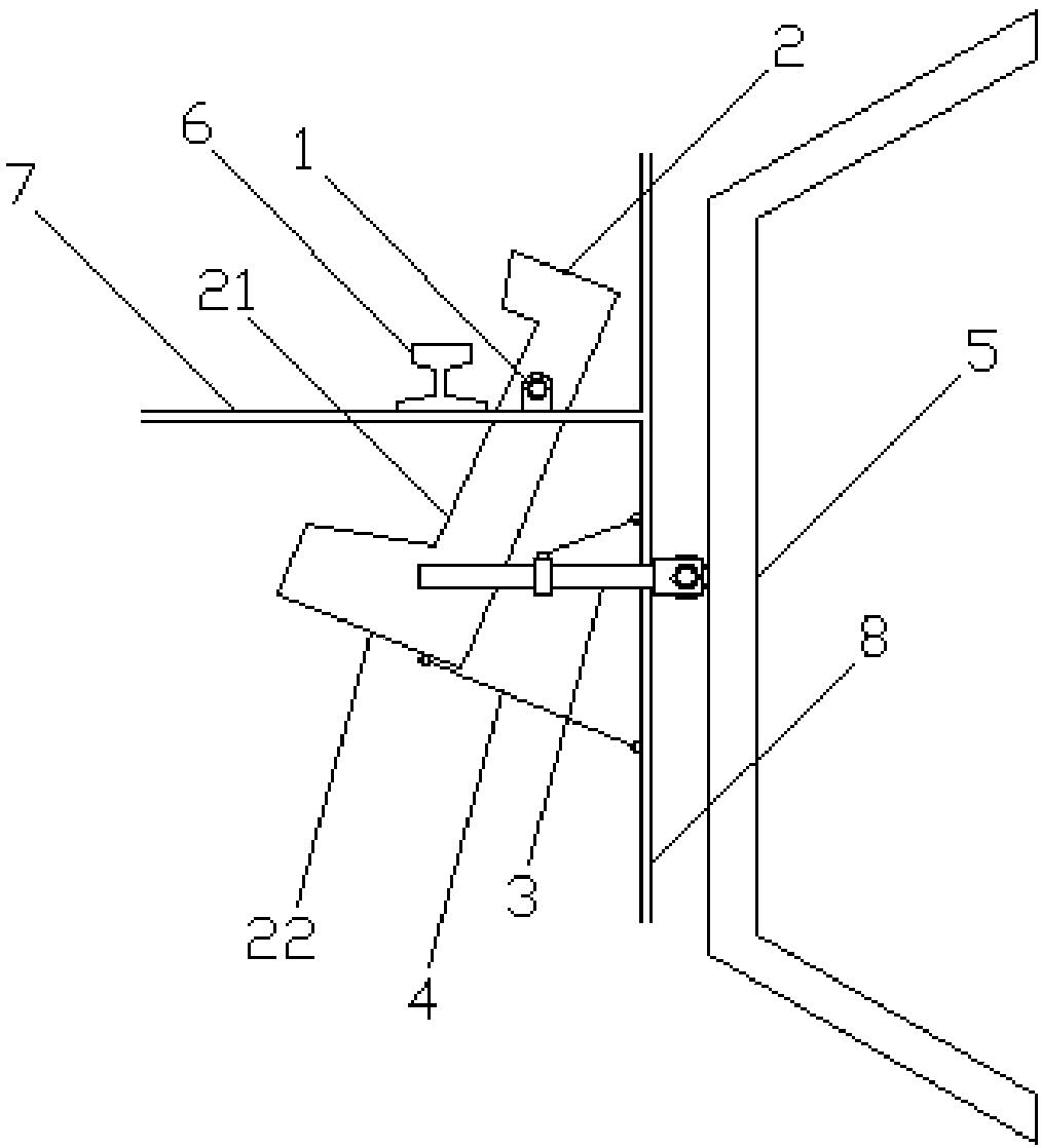
[0029] Such as Figure 1-5 As shown, a cage car arrester includes a base 1 , a baffle 2 , a control rod 3 , an elastic mechanism 4 and a guide rail 5 .

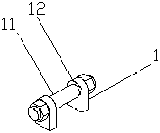
[0030] The base 1 includes a seat shaft 11 and a support plate 12, the seat shaft 11 adopts M16×92mm bolts, and the support plate 12 adopts a 10mm thick steel plate.

[0031] Two support plates 12 are arranged oppositely, and are welded on the top of the cage bottom plate 7 and the outside of the cage rail 6 .

[0032] The seat shaft 11 passes through the holes on the two support plates 12 and is connected between the two support plates 12 , and is fixed by two nuts respectively located outside the two support plates 12 , and a washer is arranged between the nuts and the support plates 12 .

[0033] The seat shaft 11 is parallel to the direction of the cage rail 6, the distance between the central axis of the seat shaft 11 and the cage bottom plate 7 is 25 mm, and the distance from the side plate 8 is 110 mm, and the side pl...


PUM


Abstract

The invention discloses a cage car stopper. The cage car stopper comprises a base, a baffle, a control rod and an elastic mechanism. The base comprises a base shaft. The middle portion of the baffle penetrates the seat shaft in a sleeving manner, the upper portion of the baffle is located above a cage bottom plate, the lower portion of the baffle penetrates the lower portion of the cage bottom plate, and the baffle rotates along the plane perpendicular to the cage track direction. One end of the control rod is connected with the lower portion of the baffle, and the other end of the control rod penetrates out of a side plate. The end, penetrating out of the side plate, of the control rod is connected with a rolling mechanism, and the rolling mechanism rolls up and down along a guide rail fixed to the position of a well mouth. One end of the elastic mechanism is connected with the part, in a tank below the cage bottom plate, of the cage car stopper, and the other end of the elastic mechanism is connected with the inner side of the part, located below the cage bottom plate, of the side plate. When the rolling mechanism is located on the point, relatively closest to the side plate, of the guide rail, the elastic mechanism is tensioned, and the upper portion of the baffle gets away from a cage track; and after the rolling mechanism leaves the guide rail, the upper portion of the baffle is clamped on the cage track. The cage car stopper has the beneficial effect that the automatic car stopping function can be achieved.

Description

technical field [0001] The invention relates to a vehicle arrester, in particular to a cage vehicle arrester. Background technique [0002] In the process of transporting the vehicles in the cage of the auxiliary well, in order to prevent the vehicles from jumping out of the cage, two wedge-shaped bosses are provided on the two rail surfaces of the inner track in the tank, and the wheels are stuck between the wedge-shaped bosses, and one end of the vehicle The two wheels of the car are blocked by the sliding car stopper. [0003] Because the wedge-shaped boss in the cage is worn by the wheel due to long-term use, its inclination and height change, once the cage shakes, stops or other abnormal conditions occur during operation, the wheel cannot be effectively blocked by the wedge-shaped boss and the sliding car stopper , the vehicle may escape from the cage, and the materials or equipment loaded on the vehicle may also slide down and escape from the cage with the movement of...

Claims


Application Information

Patent Timeline
Patent Type & Authority Patents(China)
IPC IPC(8): B66B17/22
CPCB66B17/22
Inventor 程友胜薛磊韩宝印刘成业
Owner HUAINAN MINING IND GRP
Learn More