Measuring method for track errors of robot

A measurement method and robot technology, applied in the direction of manipulators, program-controlled manipulators, manufacturing tools, etc., can solve problems such as narrow application fields

Active Publication Date: 2017-03-29
TONGJI UNIV
View PDF11 Cites 27 Cited by
  • Summary
  • Abstract
  • Description
  • Claims
  • Application Information

AI Technical Summary

Problems solved by technology

The device of this invention can only detect the motion error of the robo

Method used


Image

  • Measuring method for track errors of robot
  • Measuring method for track errors of robot
  • Measuring method for track errors of robot

Examples


Embodiment 1

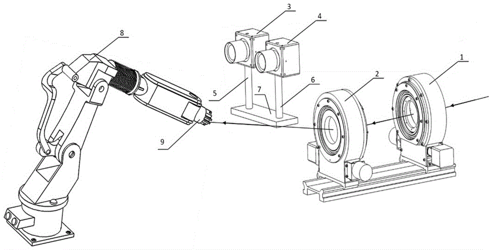
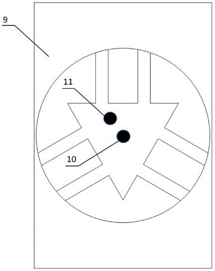
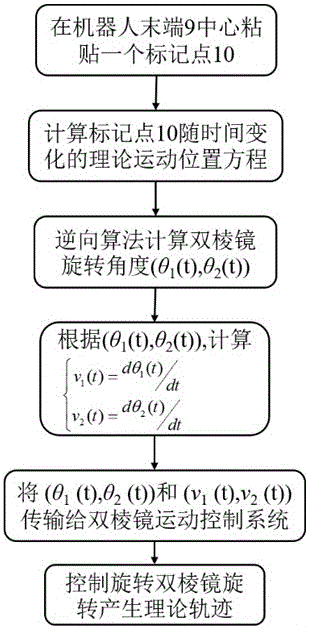
[0053] The invention provides a method for measuring robot trajectory error, which can realize the measurement of the robot's full-range or local maximum motion error: during the robot's motion process, the actual motion trajectory of the robot end is collected in real time through the visual imaging system throughout the entire process, and at the same time, the trajectory generator generates the motion of the robot. Theoretical trajectory, by comparing the two trajectories, the maximum motion error of the robot in a certain period of time or in the whole process can be obtained.

[0054] 2. The object of the present invention is achieved through the following parts: a binocular vision measurement system comprising a rotating double prism system for a trajectory generator and trajectory image acquisition. According to the theoretical motion trajectory of the robot, the rotating double prism produces a high-precision beam scanning trajectory that is irradiated on the end of the...


PUM


Abstract

The invention relates to a tracking measuring method for track errors of a robot. The tracking measuring method can be used for measuring whole-course or local maximum movement errors of the robot as follows: if movement errors within a certain period of time or whole-course maximum movement errors of the robot need to be measured, a version imaging system is used for acquiring an actual movement track of the robot end throughout the whole course and an academic track generated by a track generator in real time in a movement process of the robot; and the two tracks are compared, so that the movement errors within certain period of time or the whole-course maximum movement errors of the robot can be obtained. The measuring method can be used for measuring movement errors of a key discrete point in the movement process of the robot as follows: in the movement process of the robot, the robot is controlled to stop movement on certain key point; the version imaging system is used for acquiring coordinates of an actual spatial point at this moment of the robot, and coordinates, generated by the track generator, of an academic spatial point in real time; and a distance between the points is calculated, so that the movement errors, at the key discrete point, of the robot can be obtained. The tracking measuring method is adopted for carrying out real-time error measurement on the movement track of the robot end in the movement process of the robot.

Description

technical field [0001] The invention relates to a method for measuring robot motion track errors, in particular to a method for measuring robot track errors combining a track generator and a visual measurement system. Background technique [0002] Prior technology (Mechanical Science and Technology, Issue 2, 2011, Volume 20, Page 252, Qian Ruiming "Research on Dynamic Error Integrated Laser Measurement and Compensation of Flexible Robots") proposes a method based on 3 laser generators and 3 lasers The dynamic error measurement method of the flexible member of the position detector (PSD), the method can measure five deformation components except the rod length direction, and the optical path and measurement model are simple; the position of the light point on the PSD and the error components of the member and The relationship between the dynamic errors of the robot end effector and its compensation control method are given. However, its control process is complex and the cal...

Claims


Application Information

Patent Timeline
IPC IPC(8): B25J19/02B25J9/16
CPCB25J9/1653B25J9/1674B25J19/02
Inventor 李安虎左其友
Owner TONGJI UNIV
Why Eureka
Try Eureka