Slide rail assembly

A slide rail assembly and stopper technology, which is applied to home appliances, furniture parts, drawers, etc., can solve the problems of inconvenient maintenance and operation of the chassis

Active Publication Date: 2018-12-04
KING SLIDE WORKS CO LTD +1
View PDF6 Cites 0 Cited by
  • Summary
  • Abstract
  • Description
  • Claims
  • Application Information

AI Technical Summary

Problems solved by technology

[0004] However, when it is necessary to operate in a limited space, the aforementioned three-knot type telescopic slide rail assembly carries the chassis, so that when the chassis is pulled out from the cabinet to the outside of the cabinet by means of the slide rail assembly and fully unfolded, it will cause damage to the cabinet. The maintenance operation of the chassis is inconvenient

Method used


Image

  • Slide rail assembly
  • Slide rail assembly
  • Slide rail assembly

Examples


Embodiment Construction

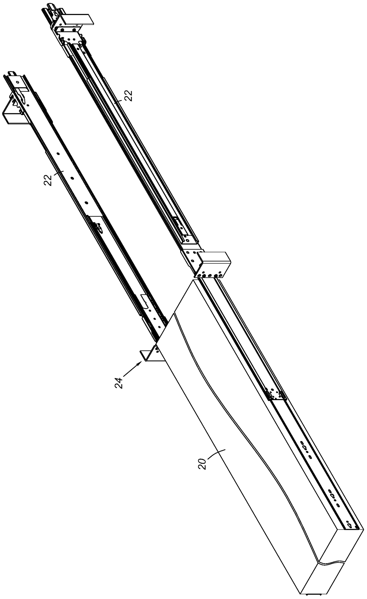
[0029] figure 1 A chassis (chassis) 20 showing an embodiment of the present invention is mounted to a rack (rack) 24 by means of a pair of slide rail assemblies 22, and the opening stroke length of the slide rail assembly 22 is fully expanded so that the chassis 20 The pair of slide rail assemblies 22 can be completely displaced outside the frame 24 .

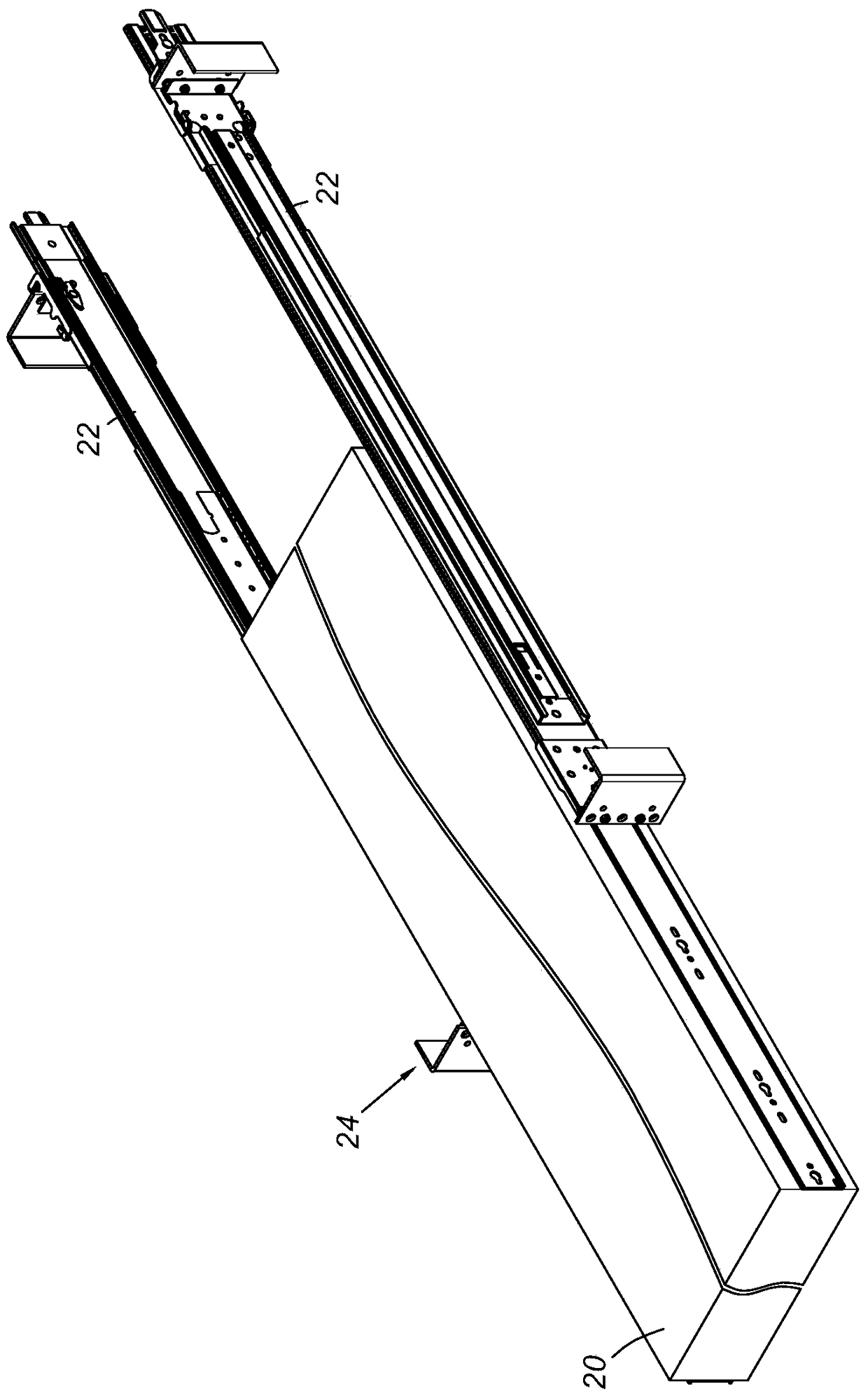
[0030] figure 2 It shows that the length of the opening stroke of the embodiment of the present invention is adjusted and shortened through the slide rail assembly 22, so that the chassis 20 can only be displaced to a part outside the frame 24, compared to figure 1 The operating mode only occupies a small opening space.

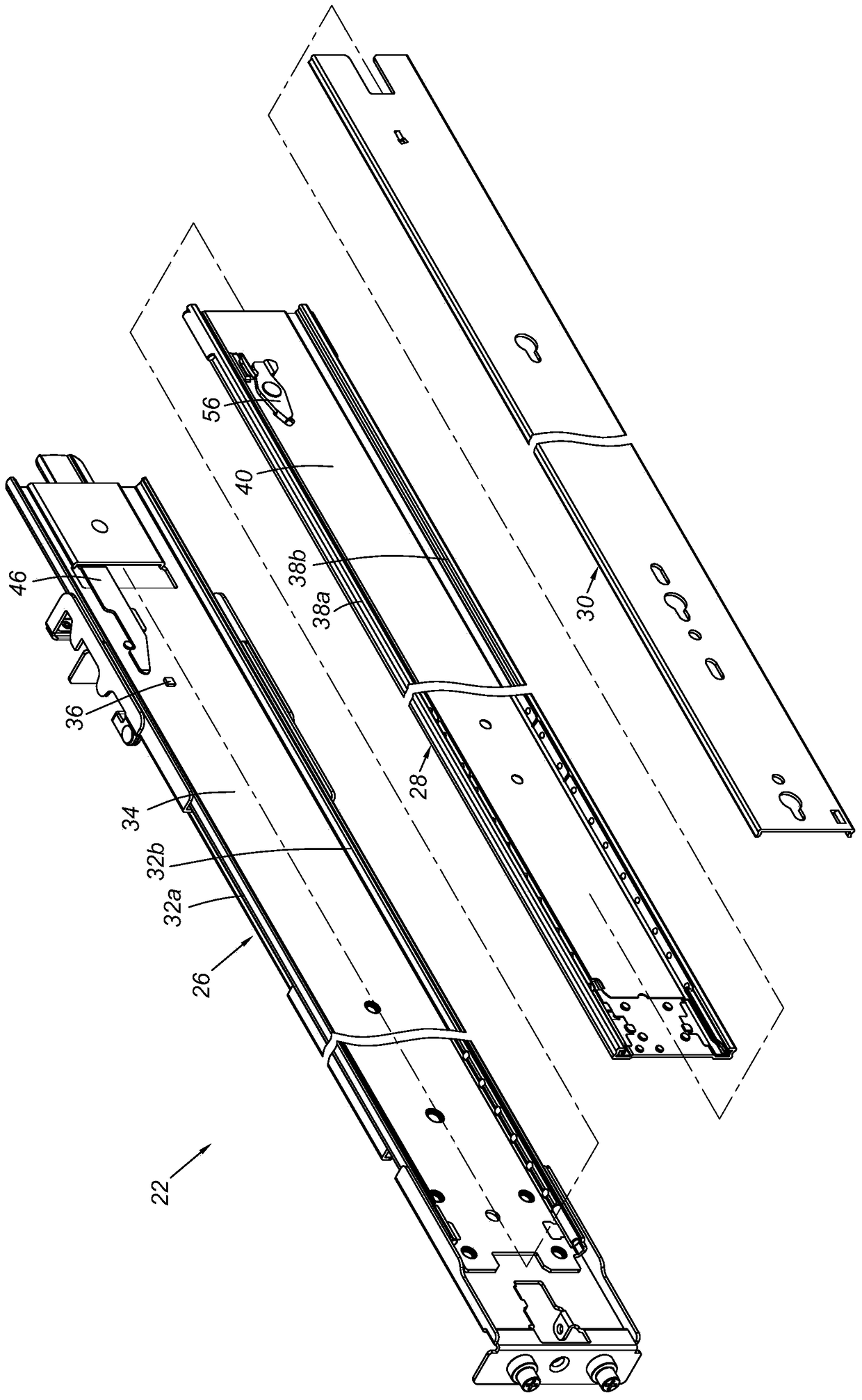
[0031] image 3 The slide rail assembly 22 illustrating an embodiment of the present invention includes a first rail 26 , a second rail 28 and a third rail 30 . Wherein, the first rail 26 has a first upper wall 32a, a first lower wall 32b, and a first side wall 34 connected between the first upper wall 32...


PUM


Abstract

The invention relates to a slide rail assembly including a first rail, a second rail, a third rail, a stopper and a clamping member. The first rail is provided with a stopping part. The second rail is movably connected with the first rail. The stopper is connected with the second rail. When the second rail is on a folded position relative to the first rail, the clamping member is connected with the stopper in an operable manner, and the stopper moves from a first predetermined position to a second predetermined position relative to the second rail and faces the stopping part of the first rail. When the slide rail assembly moves towards an opening direction, only the third rail can move relative to the second rail, and the opening stroke length of the slide rail assembly can be adjusted.

Description

technical field [0001] The invention relates to a slide rail assembly, in particular to a slide rail assembly capable of adjusting the opening stroke length. Background technique [0002] The U.S. patent U.S.6,997,529B1 invented by Chen et al. discloses a synchronous device for a three-stage slide rail. The main body of the slide rail is a carrying rail that is inserted into a fixed rail and is used to carry a movable rail. , so that the movable rail and the carrying rail can reciprocate along the same axis direction relative to the fixed rail, wherein a linking piece is pivotally arranged at the rear of the carrying rail, the movable rail is provided with a lug relative to the linking piece, and the There is a release piece on the fixed rail. When the movable rail is stretched, the protruding piece can hold against the linking piece, so that it slides synchronously with the carrying rail, and then pushes against the offset of the linking piece with the help of the release p...

Claims


Application Information

Patent Timeline
Patent Type & Authority Patents(China)
IPC IPC(8): A47B88/49H05K7/18
Inventor 陈庚金杨顺和何俊毅王俊强
Owner KING SLIDE WORKS CO LTD
Why Eureka
Try Eureka