An electrostatic grounding device and its application

A technology of electrostatic grounding and grounding body, which is applied in the direction of distribution device, special distribution device, liquid distribution, transportation or transfer device, etc., which can solve the problems of increasing costs and achieve the effect of cost saving

Active Publication Date: 2019-03-15
XIAN CHANGQING TECH ENG
View PDF7 Cites 0 Cited by
  • Summary
  • Abstract
  • Description
  • Claims
  • Application Information

AI Technical Summary

Problems solved by technology

These practices increase the cost

Method used


Image

  • An electrostatic grounding device and its application

Examples


Embodiment 1

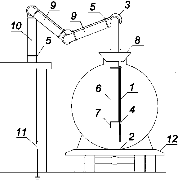
[0021] In order to overcome the problem of high cost and poor reliability existing in the existing electrostatic grounding method. This embodiment provides an electrostatic grounding device, which includes a stretchable copper rod 1, a wire, and a grounding body. The upper part of the stretchable copper rod 1 is a fixed end, and the lower part is a telescopic end. One end is connected to the grounding body, and a rubber head 2 is provided at the top of the telescopic end.

[0022] In the electrostatic grounding device provided in this embodiment, static electricity is directly introduced into the ground through the stretchable copper rod 1, the wire, and the grounding body, so as to achieve the purpose of discharge. The retractable row of the stretchable copper rod 1 can realize the adjustment of the distance between the crane tube 6 and the bottom of the tank car 12 tanks according to the capacity of the tank car, and solves the problem that the crane tube 6 is 12 tanks away ...

Embodiment 2

[0025] On the basis of Embodiment 1, this embodiment provides an electrostatic grounding device. The stretchable copper rod 1 is composed of a plurality of copper pipes whose diameters gradually increase and are connected in sequence.

[0026] The top end of the telescopic end of the telescopic copper rod 1 is a solid copper rod, and the cross-sectional area of ​​the telescopic end is 16-25 mm 2 . The wire is an annealed copper wire 3 with a cross-sectional area of ​​16-25 mm 2 .

Embodiment 3

[0028] On the basis of the electrostatic grounding device provided in Embodiment 1 or Embodiment 2, this embodiment provides an application of the electrostatic grounding device, which is used in conjunction with the crane tube 6 to discharge static electricity, the static grounding device is fixed on the outer wall of the crane tube 6.

[0029] The static grounding device is applied to the tank car 12 to discharge static electricity, the oil product is directly in contact with the stretchable copper rod 1, and the static electricity generated by the crane tube head 7 in the tank and the surface of the oil product directly passes through the stretchable copper rod 1 and the soft copper wire 3 , into the grounding body, to directly connect the oil product, the 6 heads of the crane tube and the ground, eliminating the need for intermediate contact links, and no need for resistance detection, which greatly saves costs.


PUM


Abstract

The invention provides an electrostatic grounding device. The electrostatic grounding device comprises a retractable copper bar, a wire and a grounding body, wherein the upper part of the retractable copper bar is a fixed end while the lower part of the retractable copper bar is a retractable end; the fixed end is connected with the wire; the other end of the wire is connected with the grounding body; and a rubber head is arranged on the top of the retractable end. By the electrostatic grounding device, static electricity is directly guided to the ground through the retractable copper bar, the wire and the grounding body, and therefore, the purpose of releasing the static electricity is achieved. The retractable copper bar is retractable, the distance between a crane pipe and the bottom of a tank of a tank car can be adjusted according to the capacity of the tank car, and the problems that the height of the crane pipe is fixed so that the distance between the crane pipe and the bottom of the tank of the large-capacity tank car is long, and a large amount of static electricity is easily generated on the surface of an oil product are solved. By the tank car static electricity releasing device, the oil product, the head of the crane pipe and the ground are connected directly, middle contact links are omitted, resistance detecting is not required, and costs are greatly saved.

Description

technical field [0001] The invention belongs to the technical field of electrostatic discharge of tank cars, and in particular relates to an electrostatic grounding device and its application. Background technique [0002] The current electrostatic grounding device for tank trucks is clamped on the vehicle body by electrostatic grounding clamps, and connected to the grounding body by soft copper wires. The static electricity generated in the tank during loading is introduced into the earth through the contact between the oil product and the metal of the tank body, and the contact of the static grounding clamp clamped on the car body, so as to achieve the purpose of discharge. [0003] Since the height of the loading crane tube is fixed, and the capacity of the tank car is different, the crane tube is too high from the bottom when the large-capacity tank car is loaded, and it is easy to generate a lot of static electricity on the surface of the oil product. When the conductiv...

Claims


Application Information

Patent Timeline
Patent Type & Authority Patents(China)
IPC IPC(8): B67D7/32
CPCB67D7/3236
Inventor 翟龙赵志刚姚国生谭滨蒋亚锋李小川任敏李兴华吕阳伟
Owner XIAN CHANGQING TECH ENG
Why Eureka
Try Eureka