
Split blended winglet

A technology of winglets and wingtips, applied in the field of split-fused winglets, which can solve problems such as increasing wing bending moments

Active Publication Date: 2017-04-26
AVIATION PARTNERS INC
View PDF12 Cites 1 Cited by
  • Summary
  • Abstract
  • Description
  • Claims
  • Application Information

AI Technical Summary

Problems solved by technology

While winglets reduce drag from wingtip vortices, winglets create lift, increasing the bending moment on the wing

Method used


Image

  • Split blended winglet
  • Split blended winglet
  • Split blended winglet

Examples


Embodiment Construction

[0048] In the following description, numerous specific details are set forth in order to provide a thorough understanding of the present invention. It will be apparent, however, to one skilled in the art that the present invention may be practiced without these specific details. In other cases, specific numerical references may be made, such as "first winglet". However, specific numerical references should not be construed as a literal ordinal order, but rather that a "first winglet" is different from a "second winglet". Accordingly, the specific details set forth are examples only. Specific details may be varied and still be contemplated within the spirit and scope of the invention. The term "coupled" is defined to mean directly connected to a component or indirectly connected to a component through another component. Furthermore, as used herein, the term "about", "approximately" or "substantially" for any numerical value or range indicates a suitable value that allows a p...


PUM


Abstract

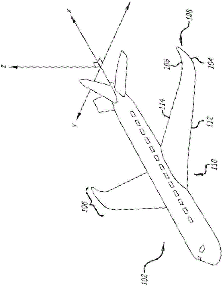
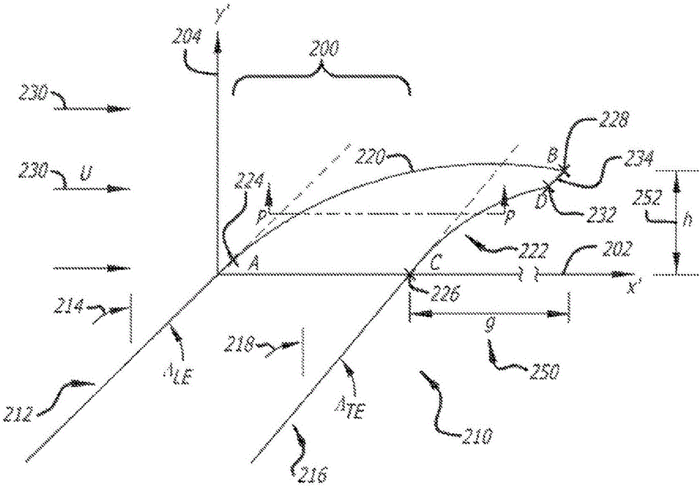
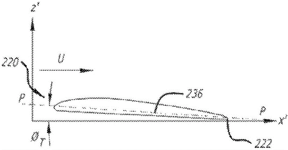
A split winglet configured for attachment to a wing of an airplane. The split winglet may include an upper winglet smoothly extending from the wing tip above a chord plane of the wing and a ventral fin projecting below the chord plane from a lower surface of the upper winglet. The upper winglet may include a transition section which curves upward from the wing tip into a substantially planar section. Upper and lower surfaces of the upper winglet may be bounded by leading and trailing edges which are swept toward an airstream direction, parallel with the chord plane, and curve toward the airstream direction before terminating at a point distal of the wing tip. Similarly, upper and lower surfaces of the ventral fin may be bounded by leading and trailing edges which curve toward the airstream direction and terminate at a point distal of the wing tip.

Description

[0001] priority [0002] This application claims priority and benefit to U.S. Patent Application No. 14 / 452,424, filed August 5, 2014, which is a continuation-in-part of U.S. Patent Application No. 12 / 488,488, filed June 19, 2009, which The U.S. Patent Application claims the benefit of U.S. Provisional Application No. 61 / 074,395, filed June 20, 2008; and is also a continuation-in-part of U.S. Patent Application No. 13 / 493,843, filed June 11, 2012, which The application claims the benefit of US Provisional Application No. 61 / 495,236, filed June 9, 2011. Each of the aforementioned applications is incorporated by reference into this application in its entirety. Background technique [0003] All aircraft wings experience resistance as they move through the air. The drag experienced can be divided into three components: induced drag, parasitic drag, and compressive drag. Induced drag depends on the lift carried by the lifting surface. Parasitic drag arises from the contact bet...

Claims


Application Information

Patent Timeline
Patent Type & Authority Applications(China)
IPC IPC(8): B64C23/06
CPCB64C23/069Y02T50/10Y02E10/72B64C23/065
Inventor L·B·格拉泽
Owner AVIATION PARTNERS INC
Learn More