Small and medium size boiling type ready-packaged organic carrier heating furnace

An organic carrier, boiling technology, used in lighting and heating equipment, combined devices, gas treatment, etc., can solve the problems of insufficient exhaust gas, increased production costs of enterprises, high oxygen content in the furnace, and reduce the heat emission temperature. , the effect of reducing production costs and reducing emissions and pollution

Active Publication Date: 2017-05-10
JIANGSU JINCHENZHEN TEXTILE
View PDF6 Cites 2 Cited by
  • Summary
  • Abstract
  • Description
  • Claims
  • Application Information

AI Technical Summary

Problems solved by technology

[0003] The use of heat conduction oil heating furnace can not be replaced by other thermal energy equipment at present, but the chain grate has the problem that the fuel cannot be burned out, that is, the furnace has high oxygen content and high nitrogen oxide content. At the same time, the fuel cannot be burned completely and the thermal efficiency is low. , resulting in an increase in the production cost of the enterprise, and at the same time, its exhaust gas cannot meet the energy-saving and emission-reduction requirements advocated by the state; as my country's environmental protection requirements become higher and higher, and the implementation is becoming more and more strict, chain grate boilers are no longer suitable for my country's environmental protection and industrial production requirements

Method used


Image

  • Small and medium size boiling type ready-packaged organic carrier heating furnace
  • Small and medium size boiling type ready-packaged organic carrier heating furnace
  • Small and medium size boiling type ready-packaged organic carrier heating furnace

Examples


Embodiment 1

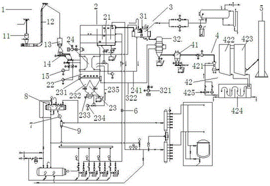
[0032] It is estimated that the heat output is 8 million kcal. A feed auger 14 is set between the feed silo 13 and the furnace 2, and the biomass fuel is sent to the feed silo through the crane 11 and the chain lift 12 to avoid fuel The discharge port of the feed silo 13 is blocked. The two sides of the feed silo 13 are provided with air hammers. The air hammers move relative to each other in a pulse type to keep the discharge port unobstructed. The fuel is sent into the furnace 2 through the feed auger 14, and a fuel blower 15 is provided under the feed auger 14. The blower blows the lighter fuel into the air when it enters the furnace 2, so that the fuel can be in the air. Combustion avoids the problem of uneven temperature of the furnace 2 caused by fuel deposits at the bottom of the furnace 2, and can also ensure the adequacy of fuel combustion.

[0033] Heavier fuel sinks and burns in the fuel combustion zone 22 at the bottom of the furnace 2. In addition to the fuel combust...

Embodiment 2

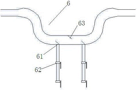
[0037] Such as figure 2 The sludge separator 6 shown is arranged between the hot oil heater 21 and the oil inlet and outlet device. The sludge separator 6 has a concave structure, and the bottom of the sludge separator 6 is provided with a sewage port 61, the sewage port 61 and the sewage valve 62 The pipe diameter is 40% larger than that of the oil pipe. The upper and lower walls of the sludge separator 6 are respectively provided with mud baffle plates 63, wherein the upper wall mud baffle plate 63 forms an angle of 130° with the oil inlet direction; The mud baffle plate 63 forms an angle of 40° with the oil inlet direction; the radial cross-sectional area of ​​the mud baffle plate 63 is 1 / 3 of the radial cross-sectional area of ​​the inner wall of the sludge separator 6; the oil of the hot oil heater 21 passes through the oil pipe through the sludge separation The pipe diameter of the sludge separator 6 is 40% larger than the pipe diameter of the oil pipe, which increases th...

Embodiment 3

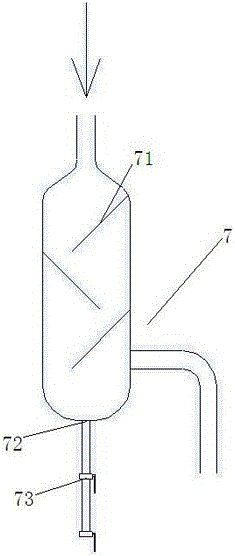
[0039] Such as image 3 The oil-water separator 7 shown is arranged in the oil inlet and outlet device, the oil inlet and outlet device includes an expansion tank 8, an oil pressure balance tank 9, and an oil and water separator 7 is provided between the expansion tank 8 and the oil pressure balance tank 9. The oil-water separator 7 is a bottle-shaped structure with a blocking plate 71 inside which forms an angle of 130° with the oil inlet direction. The radial section area of ​​the blocking plate 71 is the radial section of the inner wall of the oil-water separator 7 2 / 3 of the area, the bottom of the oil-water separator 7 is provided with an oil discharge port 72, which is connected to the oil discharge valve 73; the heat conduction oil discharged from the oil pressure balance tank 9 first enters the oil-water separator 7, and the oil-water separator 7 The weight of water, oil residue, and oil sludge is deposited at the bottom of the oil-water separator 7 to prevent them from ...


PUM


Abstract

The invention discloses equipment comprising a feeding device, a hearth, a waste heat device, a tail gas treatment device and a chimney connected in sequence, wherein the lower portion in the hearth is a fuel combustion area connected with a quartz sand circulating system; a hot oil heater is arranged at the upper portion in the hearth, and connected with an oil feeding and draining device via an oil pipe; the outlet of the hot oil heater is connected with a steam generator of the waste heat device, and the outlet of the steam generator is connected with the inlet of an air preheater; the steam generator and a steam pipe forms a fluidized bed circular protection system arranged between the hot oil heater and the fuel combustion area; and the tail gas treatment device comprises a multi-pipe dust remover and circular cleaning equipment connected in sequence. The hearth, the waste heat device, the tail gas treatment device and the chimney are connected in sequence, so that ash generated during a combustion process in the hearth can be effectively deposited under the effect of the waste heat device and the tail gas treatment device, the thermal discharge temperature of the chimney can also be further reduced, and emission pollution generated by the heating furnace is reduced, and environment protection is facilitated.

Description

Technical field [0001] The invention relates to a quick loading heating furnace, in particular to a medium and small boiling type quick loading organic carrier heating furnace. Background technique [0002] The main function of the organic carrier heating furnace is to replace hot air furnaces and general steam furnaces for industrial production heating. The history of heat transfer oil production in my country began in the mid-1970s. So far, general industrial energy supply equipment is using organic carrier heating furnaces transformed from chain grate to reach industrial temperatures. With the advancement of heating furnace technology, my country has been able to produce heat-conducting oil heating furnaces ranging from 200,000 kcal to 30 million kcal. Among them, 90% are combustion methods based on chain grate, and the rest are manual feeding combustion methods. [0003] The heating furnace using heat transfer oil cannot be replaced by other thermal energy equipment at present...

Claims


Application Information

Patent Timeline
Patent Type & Authority Applications(China)
IPC IPC(8): F23C10/18F23C10/22F23J15/06F23J15/00F23J11/00F23L15/00B01D50/00B01D53/75B01D53/78B01D53/50B01D53/56
CPCB01D53/50B01D53/56B01D53/75B01D53/78F23C10/18F23C10/22F23J11/00F23J15/006F23J15/06F23L15/00B01D2258/0283B01D50/60Y02E20/34
Inventor 季章先殷金华王晓兰
Owner JIANGSU JINCHENZHEN TEXTILE
Why Eureka
Try Eureka