Fast dual-probe atomic force microscope approximation device and fast dual-probe atomic force microscope approximation method

An atomic force microscope and dual-probe technology, applied in scanning probe microscopy, measuring devices, scanning probe technology, etc., can solve time-consuming and labor-intensive problems, simplify steps, save time and effort in operation, and speed up the approach adjustment process Effect

Active Publication Date: 2017-05-10
THE NAT CENT FOR NANOSCI & TECH NCNST OF CHINA +1
View PDF15 Cites 7 Cited by
  • Summary
  • Abstract
  • Description
  • Claims
  • Application Information

AI Technical Summary

Problems solved by technology

[0005] The purpose of the present invention is to propose a dual-probe atomic force microscope fast approximation device and method to solve the technical problems in the prior art that the laser needs to be adjusted multiple times during the approximation process, which is time-consuming and labor-intensive.

Method used


Image

  • Fast dual-probe atomic force microscope approximation device and fast dual-probe atomic force microscope approximation method
  • Fast dual-probe atomic force microscope approximation device and fast dual-probe atomic force microscope approximation method
  • Fast dual-probe atomic force microscope approximation device and fast dual-probe atomic force microscope approximation method

Examples


Embodiment 1

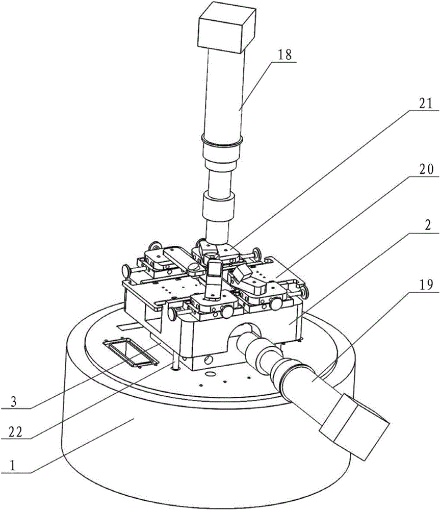
[0038] Such as Figure 3-5 As shown, a double-probe atomic force microscope rapid approach device includes a microscope base 1, a detection head base 2 is arranged on the microscope base 1, the detection head base 2 is connected to the microscope base 1 through a lifting assembly, and the microscope base 1 is connected to the detection A sample scanning platform 3 is provided between the head bases 2, a sample table 4 for placing samples is provided on the sample scanning platform 3, and a master probe assembly and a slave probe assembly are provided on the detection head base 2;

[0039]The main probe assembly includes a main probe 5, the main probe 5 is connected with a first cantilever beam 6, a first laser 7 and a first photoelectric receiver 8 are arranged above the first cantilever beam 6, and the first cantilever beam 6 is connected with an XY Axis micrometer positioning stage 9;

[0040] The slave probe assembly includes a slave probe 10, which is connected with a sec...

Embodiment 2

[0055] The incident light and reflected light on the first cantilever beam 6 form a plane P1, the incident light and reflected light on the second cantilever beam 11 form a plane P2, and the plane P1 and the plane P2 overlap each other. In general, the plane P1 and the plane P2 are intersecting each other, such as the two sides are perpendicular to each other. In this state, the corresponding lasers and photoelectric receivers and other components are scattered and occupy a large space, which leads to a large space occupied by the equipment as a whole. . Therefore, in order to save space to the greatest extent, the plane P1 and the plane P2 are arranged to overlap each other, that is, the two sides are parallel to each other and superimposed to achieve a superimposed state, and then the components such as the laser and the photoelectric receiver are no longer scattered, and the positions are more compact. It takes up less space.

Embodiment 3

[0057] Such as Figure 6 As shown, a two-probe AFM fast approximation method, including the following steps:

[0058] a. The main probe 5 is adjusted in the horizontal X-axis and Y-axis direction, so that the main probe 5 is close to the slave probe 10, and the slave probe 10 is adjusted along the vertical Z-axis direction, so that the slave probe 10 is lower than the master probe 5 ;

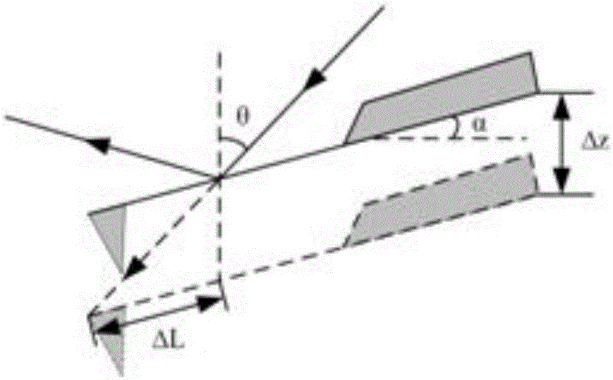
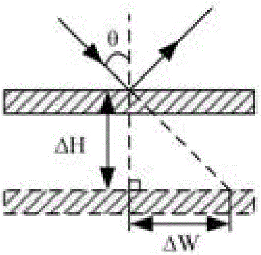
[0059] b. Adjust the lasers of the main probe 5 and the slave probe 10 respectively, so that the incident light spot of the laser is located at the midpoint of the front end of the cantilever beam of the main probe 5 and the cantilever beam of the slave probe 10, and the reflected light spot is located at the cross of the photoelectric receiver point, wherein the light emitted from the laser of the probe 10 is reflected by the mirror 13, and the spot of the light is shot vertically on the cantilever beam from the probe 10;

[0060] c. Move the main probe 5, the slave probe 10, the laser and t...


PUM


Abstract

The invention relates to the technical field of physical property measurement and control in micro-nano regions, in particular to a fast dual-probe atomic force microscope approximation device and a fast dual-probe atomic force microscope approximation method based on laser detection. The fast dual-probe atomic force microscope approximation method includes that a master probe is adjusted along a horizontal X-axis direction and horizontal Y-axis direction, and a slave probe is adjusted along the vertical X-axis direction; laser devices of the master probe and the slave probe are adjusted, light rays emitted by the laser device of the slave probe are reflected by a reflective mirror and light spots of the light rays are emitted on a suspension arm beam of the slave probe vertically. The method has the advantages that incident light of the slave probe needing Z-axis adjustment is adjusted to be incident vertically by the reflective mirror, and accordingly deviation from the suspension arm can be avoided during adjustment, the laser devices only need to be adjusted once, and the approximation method is greatly simplified; then, the master probe and the slave probe are adjusted finely until both of the two probes contact with a sample, and then approximation operation is completed.

Description

technical field [0001] The invention relates to the technical field of measurement and manipulation of physical properties in micro-nano regions, in particular to a laser detection-based dual-probe atomic force microscope rapid approach device and method. Background technique [0002] The scale range of micro-nano technology is 1nm-100nm. The measurement and manipulation of physical properties in this scale range requires specific observation and manipulation methods. The atomic force microscope (AFM) has the advantages of high resolution, simple sample preparation, and adaptability to different environments. , the most widely used. [0003] However, the traditional atomic force microscope has only one probe, and its functions are very limited. Therefore, in order to expand its application possibilities, a double-probe atomic force microscope is currently used. Among them, the double-probe can form nano-tweezers to realize the manipulation of nano-objects in three-dimension...

Claims


Application Information

Patent Timeline
Patent Type & Authority Applications(China)
IPC IPC(8): G01Q10/04G01Q60/24
CPCG01Q10/04G01Q60/24
Inventor 李鹏裘晓辉吴浚瀚王帅
Owner THE NAT CENT FOR NANOSCI & TECH NCNST OF CHINA
Why Eureka
Try Eureka