Switch-on indicating isolation switch

An isolating switch and indicating technology, which is applied in the direction of electric switches, electrical components, circuits, etc., can solve the problems of lack of indicating status and inability to judge whether the closing is in place, etc.

Inactive Publication Date: 2017-05-10
河南众联云科工程技术有限公司
View PDF6 Cites 4 Cited by
  • Summary
  • Abstract
  • Description
  • Claims
  • Application Information

AI Technical Summary

Problems solved by technology

However, most of the existing isolating switches are composed of dynamic and static contacts and a knife switch. The closing state is mostly judged manually. Manual judgments are prone to errors, and it is impossible to judge whether the closing is in place, and there is no indication state after closing.

Method used


Image

  • Switch-on indicating isolation switch
  • Switch-on indicating isolation switch

Examples


Embodiment Construction

[0013] The technical solutions of the present invention will be described in further detail below through specific implementation methods.

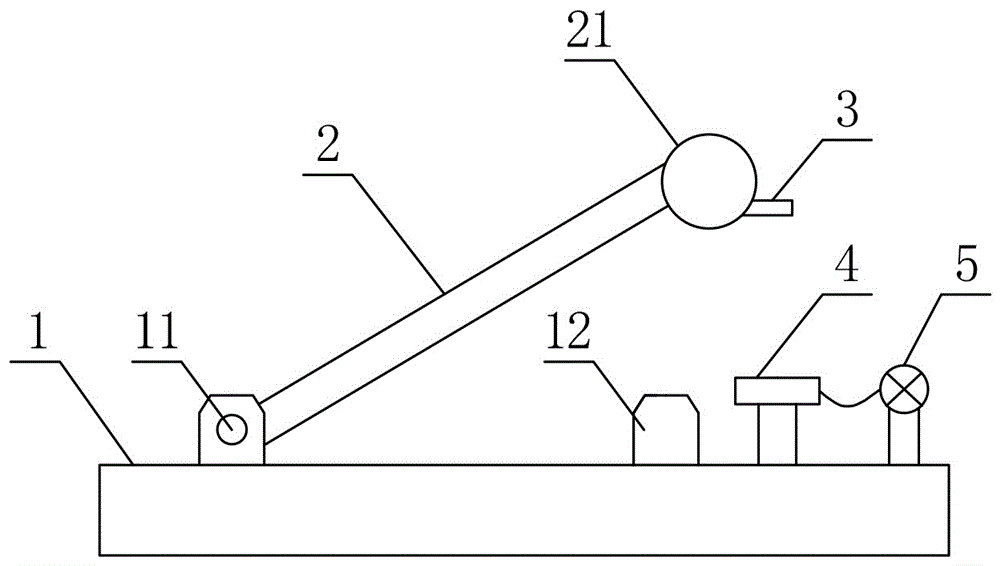
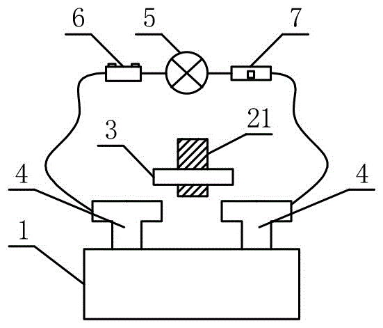
[0014] Such as figure 1 and figure 2 As shown in the figure, a closing indicating isolating switch includes a base 1, a moving contact 11 and a static contact 12 installed on the base 1. In order to ensure the monitorability of closing, the closing indicating isolating switch It also includes a knife switch 2, one end of the knife switch 2 is hinged to the movable contact 11, the other end of the knife switch 2 is fixed with an insulating operating ring 21, and one side of the insulating operating ring 21 is laterally fixed with a conductive piece 3, The base 1 is provided with a power supply 6, an indicator light 5, a delay switch 7 and a group of conductive contacts 4 arranged apart from each other, the conductive sheet 3, the power supply 6, the indicator light 5, the delay switch The hour switch 7 and a group of conductive contacts...


PUM


Abstract

The invention provides a switch-on indicating isolation switch. The switch-on indicating isolation switch comprises a base, a moving contact and a static contact which are mounted on the base, and also comprises a disconnecting link, wherein one end of the disconnecting link is hinged with the moving contact while an insulating operating ring is fixed at the other end of the disconnecting link; a conductive sheet is transversely fixed on one side of the operating insulating ring; the base is provided with a power supply, an indicator lamp, a time-delay switch and a group of conductive contacts which are arranged at intervals; and the conducive sheet, the power supply, the indicator lamp, the time-delay switch and the group of conductive contacts form an indicating loop. The switch-on indicating isolation switch has the advantages of scientific design, high practicability, simple operation, capability of monitoring a switch-on state, and good switch-on effect.

Description

technical field [0001] The invention relates to an isolating switch, in particular to a closing indicating isolating switch. Background technique [0002] As an important component of the transmission line, the isolating switch is mainly used to cooperate with the circuit breaker and other on-off transmission lines, so that the transmission line has an obvious disconnection point, so as to ensure the safety of maintenance personnel and equipment. However, most of the existing isolating switches are composed of dynamic and static contacts and a knife switch. The closing state is mostly judged manually. Manual judgments are prone to errors, and it is impossible to judge whether the closing is in place, and there is no indication state after closing. How to effectively display the closing state and ensure that the closing is in place is an urgent problem to be solved. [0003] In order to solve the above existing problems, people have been seeking an ideal technical solution. ...

Claims


Application Information

Patent Timeline
Patent Type & Authority Applications(China)
IPC IPC(8): H01H9/16
CPCH01H9/161
Inventor 李和超
Owner 河南众联云科工程技术有限公司
Why Eureka
Try Eureka