
Flow guiding umbrella

A technology of umbrellas and diversion mechanisms, applied in the direction of walking sticks, etc., can solve problems such as futility

Inactive Publication Date: 2017-05-17
UNIV OF SHANGHAI FOR SCI & TECH
View PDF4 Cites 0 Cited by
  • Summary
  • Abstract
  • Description
  • Claims
  • Application Information

AI Technical Summary

Problems solved by technology

However, on a rainy day with strong winds, it is futile to hold an umbrella

Method used


Image

  • Flow guiding umbrella
  • Flow guiding umbrella

Examples


Embodiment Construction

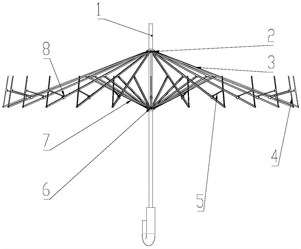
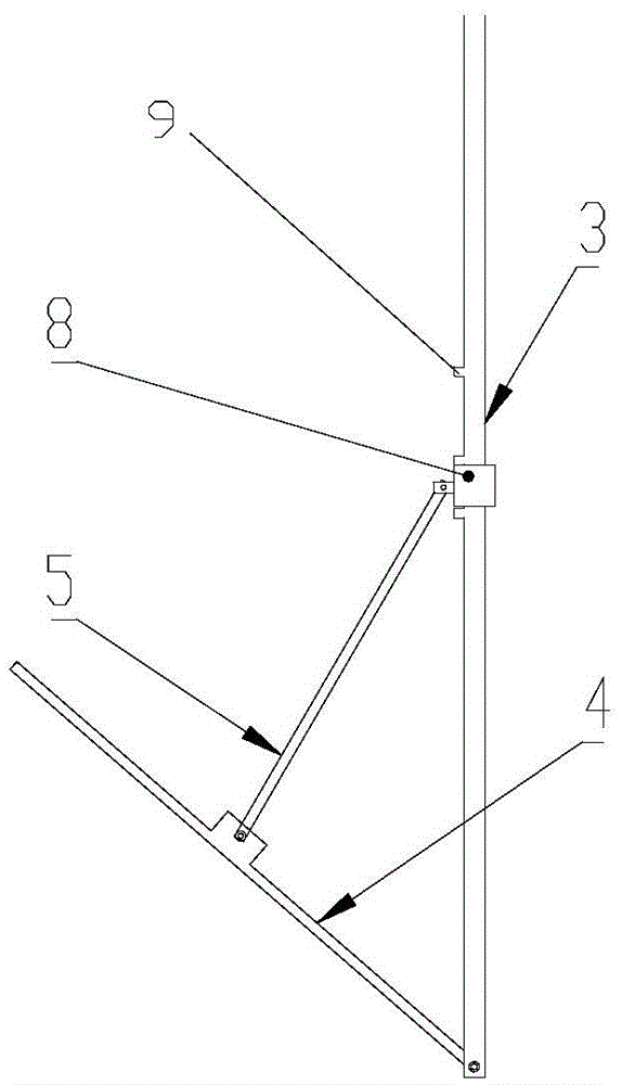
[0010] see figure 1 , figure 2 , the diversion umbrella of the present invention comprises an umbrella center rod 1, an upper fixed chuck 2, an umbrella skeleton 3, a drainage skeleton 4, an outer stretch rod 5, a lower sliding chuck 6, an inner stretch rod 7, a slider 8 and an umbrella cloth (not shown). Wherein, the drainage frame 4, the outer stretch rod 5 and the slider 8 constitute a rainwater diversion mechanism. The rainwater diversion mechanism is movably connected to the periphery of the umbrella frame 3, and forms an angle with the umbrella frame, and the umbrella cloth extends and covers the rainwater diversion mechanism, and forms a single rainwater outlet at the angle, so that The rainwater falling on the umbrella only flows out from this outlet.

[0011] In the above-mentioned rainwater diversion mechanism, each drainage frame 4 is hingedly connected with the corresponding umbrella frame 3 respectively, each slider 8 is respectively set on the corresponding u...


PUM


Abstract

The invention discloses a flow guiding umbrella, comprising an umbrella skeleton and an umbrella cloth; the umbrella further comprises a rainwater flow guiding mechanism; the rainwater flow guiding mechanism is moveably connected to the periphery of the umbrella skeleton, and forms an included angle with the umbrella skeleton; the umbrella cloth is coated on the rainwater flow guiding mechanism, and a single rainwater outlet is formed at the included angle, thus the rainwater fallen on the umbrella is only flowed from the outlet. The flow guiding umbrella is simple in structure and easy to control, thus the sunshade function of an ordinary sunshade and the rainproof function of an ordinary umbrella can be realized; meanwhile, the umbrella can control the rainwater flowing direction and guide rainwater to a fixed outlet.

Description

technical field [0001] The invention relates to daily necessities, in particular to a diversion umbrella. Background technique [0002] In life, we find that rainy days always bring me a lot of inconvenience, but many times we have to go out to do errands, so a series of "artifacts" for sunshade and rain protection came into being. From the original coir raincoat to the raincoat to the umbrella, it can be found that people not only pursue practicality, but also convenience. However, on rainy days with strong winds, it is futile to hold an umbrella. Because rainwater always flows on us from all directions, an umbrella that restricts the direction of rainwater flow and allows rainwater to flow out from a single outlet is in urgent need. Contents of the invention [0003] The object of the present invention is to provide a diversion umbrella in order to solve the above problems. [0004] In order to achieve the above object, the present invention adopts the following techn...

Claims


Application Information

Patent Timeline
Patent Type & Authority Applications(China)
IPC IPC(8): A45B25/28
CPCA45B25/28
Inventor 石更强李根生杨坤陈佳殷晨孟胡齐赵敏
Owner UNIV OF SHANGHAI FOR SCI & TECH
Learn More