
A multifunctional workpiece processing table device

A processing table, multi-functional technology, applied in the direction of workbench, manufacturing tools, etc., can solve the problems of affecting work efficiency, operator's raising and lowering adjustment, cumbersome process, etc., to achieve convenient operation, meet height and orientation adjustment, structure simple effect

Active Publication Date: 2017-11-07
TAIZHOU HUAFENG TECH EQUIP
View PDF6 Cites 0 Cited by
  • Summary
  • Abstract
  • Description
  • Claims
  • Application Information

AI Technical Summary

Problems solved by technology

[0002] At present, the workpiece processing table is often used in workpiece processing. The existing workpiece processing table is generally set in one piece, which cannot be adjusted according to the height of the operator, so that the operator is limited in operation. Due to the influence of height, it becomes very difficult. At the same time, due to the different sizes of the processed workpieces, when collecting or packing some small and large number of fragmented workpieces after processing, they need to be picked up one by one. The process is too cumbersome and greatly affects work efficiency; however, when processing some larger workpieces, it needs to meet the processing requirements of each surface of the workpiece through its own continuous movement. The engineering is too laborious and has great disadvantages , can not meet the existing needs and need to be improved

Method used


Image

  • A multifunctional workpiece processing table device
  • A multifunctional workpiece processing table device
  • A multifunctional workpiece processing table device

Examples


Embodiment Construction

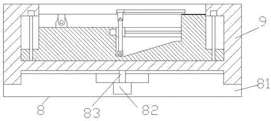
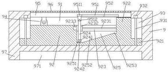
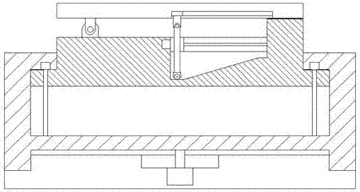
[0020] Such as Figure 1-Figure 5 As shown, a multifunctional workpiece processing table device of the present invention includes a base 8 and a processing table portion 9 arranged on the upper end of the base 8, and a protruding ring 81 is fixed on the outside of the base 8. A third motor 82 is provided at the inner center of the base 8, and the top end of the third motor 82 is rotatably connected to an upwardly extending rotating shaft 83, and the top end of the rotating shaft 83 is fixedly connected to the center of the bottom of the processing table portion 9. A protruding block 97 is fixed at the edge of the bottom of the processing table portion 9, and an annular groove 971 is arranged in the protruding block 97, and the top end of the base 8 extends into the annular groove 971 and is connected by rotation. The bottom end surface of the protruding block 97 is in contact with the top surface of the protruding ring 81 and connected in rotation. The inner top end of the pro...


PUM


Abstract

The invention discloses a multi-functional workpiece machining table device. The multi-functional workpiece machining table device comprises a pedestal and a machining table part installed at the upper end of the pedestal; a protruded ring is fixedly installed on the outer side of the pedestal, a third motor is installed in the center of the pedestal, the top end of the third motor is in rotating connection with a rotating shaft installed in an upward extending mode, and the top end of the rotating shaft is fixedly connected with the center of the bottom of the machining table part; a protruded block is fixedly installed on the edge of the bottom of the machining table part, a circular ring groove is formed in the protruded block, and the top end of the pedestal stretches into the circular ring groove and is connected with the circular ring groove in a rotary matching mode; and the bottom end face of the protruded block and the top end face of the protruded ring are connected in an against and rotary matching mode, an assembling groove is formed in the inner top end of the machining table part, and an assembling block is installed in the assembling groove. According to the multi-functional workpiece machining table device, the structure is simple, operation is convenient, while adjustment of the height and the orientation is met, the multi-functional workpiece machining table device has an automatic removing-out function, and existing requirements are met.

Description

technical field [0001] The invention relates to the technical field of processing tables, in particular to a multifunctional workpiece processing table device. Background technique [0002] At present, the workpiece processing table is often used in workpiece processing. The existing workpiece processing table is generally set in one piece, which cannot be adjusted according to the height of the operator, so that the operator is limited in operation. Due to the influence of height, it becomes very difficult. At the same time, due to the different sizes of the processed workpieces, when collecting or packing some small and large number of fragmented workpieces after processing, they need to be picked up one by one. The process is too cumbersome and greatly affects work efficiency; however, when processing some larger workpieces, it needs to meet the processing requirements of each surface of the workpiece through its own continuous movement. The engineering is too laborious a...

Claims


Application Information

Patent Timeline
Patent Type & Authority Patents(China)
IPC IPC(8): B25H1/10B25H1/16
CPCB25H1/10B25H1/16
Inventor 夏景明
Owner TAIZHOU HUAFENG TECH EQUIP
Learn More