Main pump support device for large nuclear-grade main pump test bench position

A supporting device and main pump technology, which is applied in the direction of pump testing, liquid variable displacement machinery, machine/engine, etc., can solve the problems of inconsistent length of main pipeline, troublesome installation accuracy of the main pump used in the platform, and difficult design, etc., to achieve The effect of ensuring stability, ensuring strength and safety, and ensuring contact stiffness

Active Publication Date: 2017-05-17
CHINA UNITED ENG
View PDF5 Cites 0 Cited by
  • Summary
  • Abstract
  • Description
  • Claims
  • Application Information

AI Technical Summary

Problems solved by technology

[0003] Due to the different lengths and connecting devices of the branches of the main pipeline system, the thermal expansion of the main pipeline will cause inconsistent lengths during hot operation, which will cause the pump support as a free end to slip in one-dimensional direction. There is also a small angle of rotation, while the pump support as a fixed end can be rigidly fixed to limit movement in all dimensions
Therefore, the two pump support bases are required to be able to slide in one dimension, rotate at a small angle, or be rigidly fixed, and the design is difficult. It can be seen that when the main pipeline system is tested on the large water pump test bench with two stations, The thermal displacement and small-angle rotation of the pipe support caused by the thermal expansion of the main pipe during hot operation is one of the main problems that plague the use of the platform and the installation accuracy of the main pump.

Method used


Image

  • Main pump support device for large nuclear-grade main pump test bench position
  • Main pump support device for large nuclear-grade main pump test bench position
  • Main pump support device for large nuclear-grade main pump test bench position

Examples


Embodiment

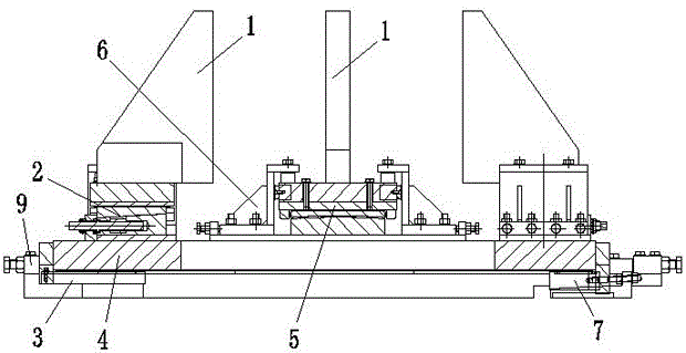
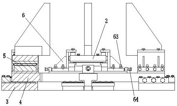
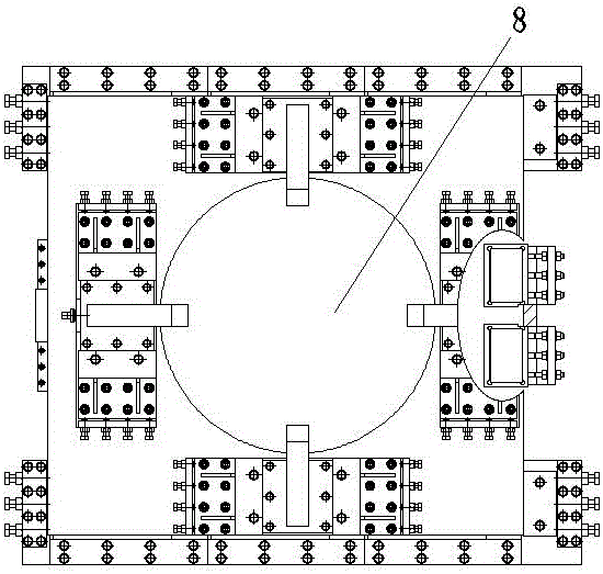
[0065] see Figure 8-Figure 10 , the pump casing A and the pump casing B are installed at both ends of the pipeline. There are two in the present invention, and the reference signs are C and D. The main pump support device C and the main pump support device D are installed on the steel structure platform. The main pump on the pump casing plays a supporting role. When testing the main pump A', the main pump supporting device C is fixed, and the relevant limit mechanism of the main pump supporting device D is loosened, so that it can freely expand and rotate at a small angle when the temperature of the pipeline system rises; when testing the main pump B' , the main pump support device D is fixed, and the relevant limit mechanism of the main pump support device C is loosened, so that it can expand freely and rotate at a small angle.


PUM


Abstract

The invention provides a main pump support device for a large nuclear-grade main pump test bench station position. The requirements on one-dimensional sliding, small-angle rotation and rigid fixing of the main pump support after the test bench position is built can be met. A bottom plate is horizontally and fixedly arranged. A seat plate is mounted on the bottom plate. A sliding block base is fixedly mounted on the seat plate. A screw is rotationally mounted on the sliding block base. A lower inclined block is horizontally and slidably mounted on the sliding block base. A cylindrical nut is mounted on the lower inclined block and connected with the screw. An upper inclined block is slidably mounted on the lower inclined block. The upper inclined face is in contact with the lower inclined face. Support plates are slidably mounted on the upper inclined block. A convex arc plate seat is fixedly mounted on the seat plate. A convex arc plate is fixedly mounted on the convex arc plate seat. A concave arc plate is slidably mounted on the convex arc plate. The concave arc face is in contact with the convex arc face. Supporting plates are fixedly mounted on the concave arc plate. Limiting bolts are mounted on limiting plates and are detachably connected with the supporting plates. Baffles are fixedly arranged on the two sides of the bottom plate. Tightening bolts are mounted on the corresponding baffles and are detachably connected with the seat plate.

Description

technical field [0001] The invention relates to a main pump support device at a large-scale nuclear-level main pump test stand, which is used as a main pump installation support in a large-scale nuclear-level main pump closed test pipeline system. Background technique [0002] Before the large-scale nuclear-grade main pump leaves the factory, the main pump needs to be placed on the test bench for a series of delivery and performance tests. Due to the extremely high construction cost of nuclear-grade main pump test benches, considering the cost of bench construction, some benches are built as closed test benches that can conduct two or more types of pump tests. At this time, the two The general-purpose pump casing of multiple pump types is welded in the test pipeline. When testing one pump type, the support of this pump is fixed, and the support is in a fixed state. As a fixed end, the pump casing support of another pump type is loose. Open, the support is in a state of free...

Claims


Application Information

Patent Timeline
Patent Type & Authority Applications(China)
IPC IPC(8): F04B51/00
CPCF04B51/00
Inventor 胡益鑫程教杨章煜君李申杰
Owner CHINA UNITED ENG
Why Eureka
Try Eureka