Lens adjusting method and lens adjusting device for head-mounted display equipment, and head-mounted display equipment

An adjustment method and display device technology, applied in optics, instruments, electrical components, etc., can solve problems such as long adjustment time and affecting user experience, and achieve the effect of reducing user operations and improving user experience

Inactive Publication Date: 2017-05-17
GEER TECH CO LTD
View PDF7 Cites 28 Cited by
  • Summary
  • Abstract
  • Description
  • Claims
  • Application Information

AI Technical Summary

Problems solved by technology

But this not only brings some extra operations to the user, but al

Method used


Image

  • Lens adjusting method and lens adjusting device for head-mounted display equipment, and head-mounted display equipment
  • Lens adjusting method and lens adjusting device for head-mounted display equipment, and head-mounted display equipment
  • Lens adjusting method and lens adjusting device for head-mounted display equipment, and head-mounted display equipment

Examples


Example Embodiment

[0045] Various exemplary embodiments of the present invention will now be described in detail with reference to the accompanying drawings. It should be noted that unless specifically stated otherwise, the relative arrangement of components and steps, numerical expressions and numerical values ​​set forth in these embodiments do not limit the scope of the present invention.

[0046] The following description of at least one exemplary embodiment is actually only illustrative, and in no way serves as any limitation to the present invention and its application or use.

[0047] The technologies, methods, and equipment known to those of ordinary skill in the relevant fields may not be discussed in detail, but where appropriate, the technologies, methods, and equipment should be regarded as part of the specification.

[0048] In all examples shown and discussed herein, any specific value should be interpreted as merely exemplary, rather than as a limitation. Therefore, other examples of th...


PUM


Abstract

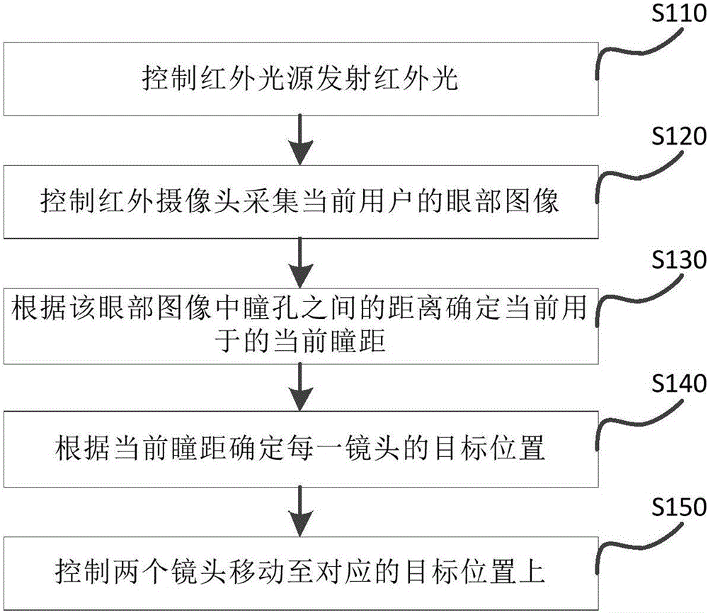
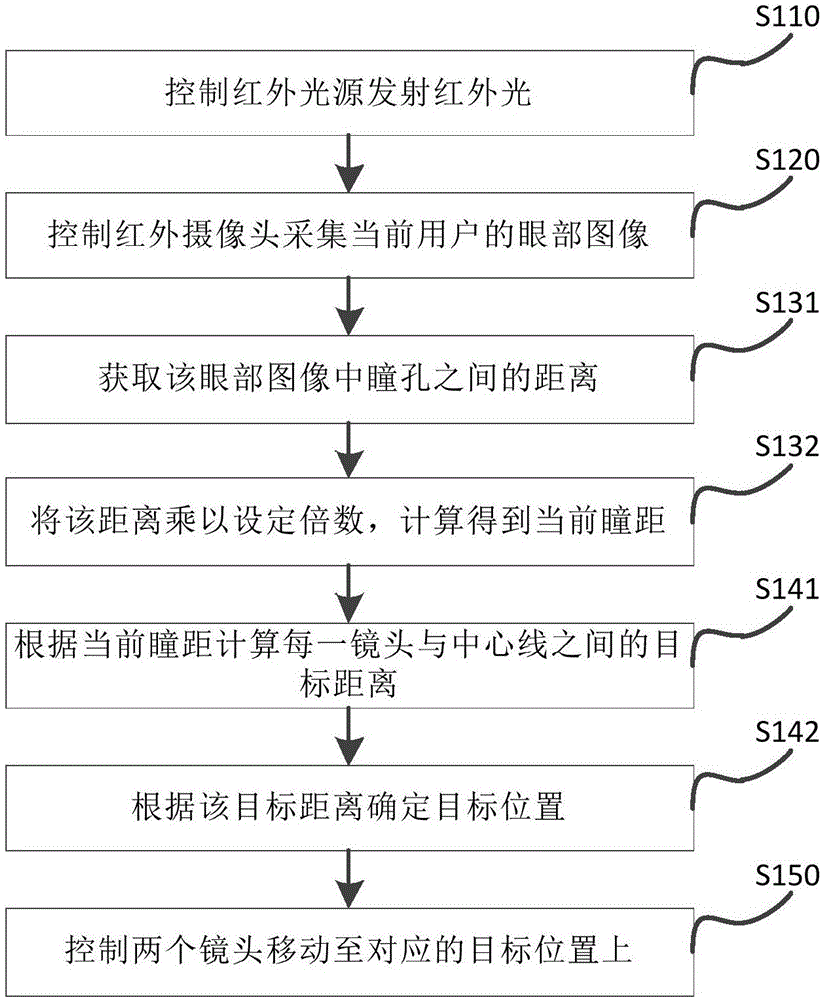
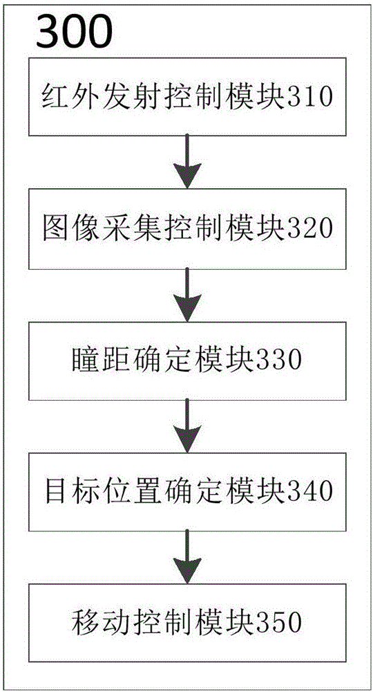
The invention discloses a lens adjusting method and a lens adjusting device for head-mounted display equipment, and head-mounted display equipment. The lens adjusting method comprises the steps of making an infrared light source emit infrared light; making an infrared camera acquire an eye image of a current user; determining the current pupillary distance of the current user according to a distance between pupils in the eye image; determining the target position of each lens according to the current pupillary distance, and making two lenses move to corresponding target positions. Through the lens adjusting method, the lens position can be automatically adjusted through detecting the pupillary distance of the user so that the user acquires a clear image, thereby reducing user operations and improving user experience.

Description

technical field [0001] The present invention relates to the technical field of head-mounted display devices, and more particularly, the present invention relates to a lens adjustment method and device for head-mounted display devices and the head-mounted display device. Background technique [0002] At present, the head-mounted display devices on the market basically use a mechanical knob to adjust the distance between the lenses and the distance between the display screens, so that the visual image changes from blurred to clear. This is because the pupillary distance of each user is different. Only by adjusting the lens and display screen to the position suitable for the pupil through the knob can a clearer image be obtained. However, this not only brings some extra operations to the user, but also may take a long time to adjust, which affects user experience. [0003] Therefore, it is very valuable to propose a solution that can automatically, quickly and accurately adjus...

Claims


Application Information

Patent Timeline
IPC IPC(8): H04N13/02H04N13/04G02B27/01
CPCH04N13/339G02B27/0172H04N13/239
Inventor 刘鑫
Owner GEER TECH CO LTD
Why Eureka
Try Eureka