Copper wire feeding device

A copper wire and rack technology is applied in the field of copper wire feeding devices, which can solve the problems of copper wire winding and disconnection, and achieve the effect of preventing copper wire winding.

Inactive Publication Date: 2017-05-24
WUXI VIGOROUS ELECTRIC
View PDF5 Cites 7 Cited by
  • Summary
  • Abstract
  • Description
  • Claims
  • Application Information

AI Technical Summary

Problems solved by technology

[0002] Wire is an essential component in electrical equipment. Generally, the wire is wrapped with an insulating plastic layer on the outside of the inner copper core. In the wire production process, the inner copper core is processed separately first, and then passed through another process. The insulating plastic layer is processed on the outside of the copper core. The inner copper core is generally formed of copper wire. After being processed separately, it will be wound on the reel. When processing is required, the reel is placed on the shelf, and then the copper wire is pulled for loading. , because the copper wire material is conveyed backward by pulling the copper wire by pulling force, sometimes the wire breakage will occur during the pulling and feeding process.

Method used


Image

  • Copper wire feeding device
  • Copper wire feeding device

Examples


Embodiment Construction

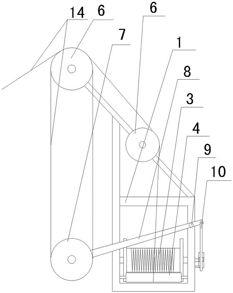
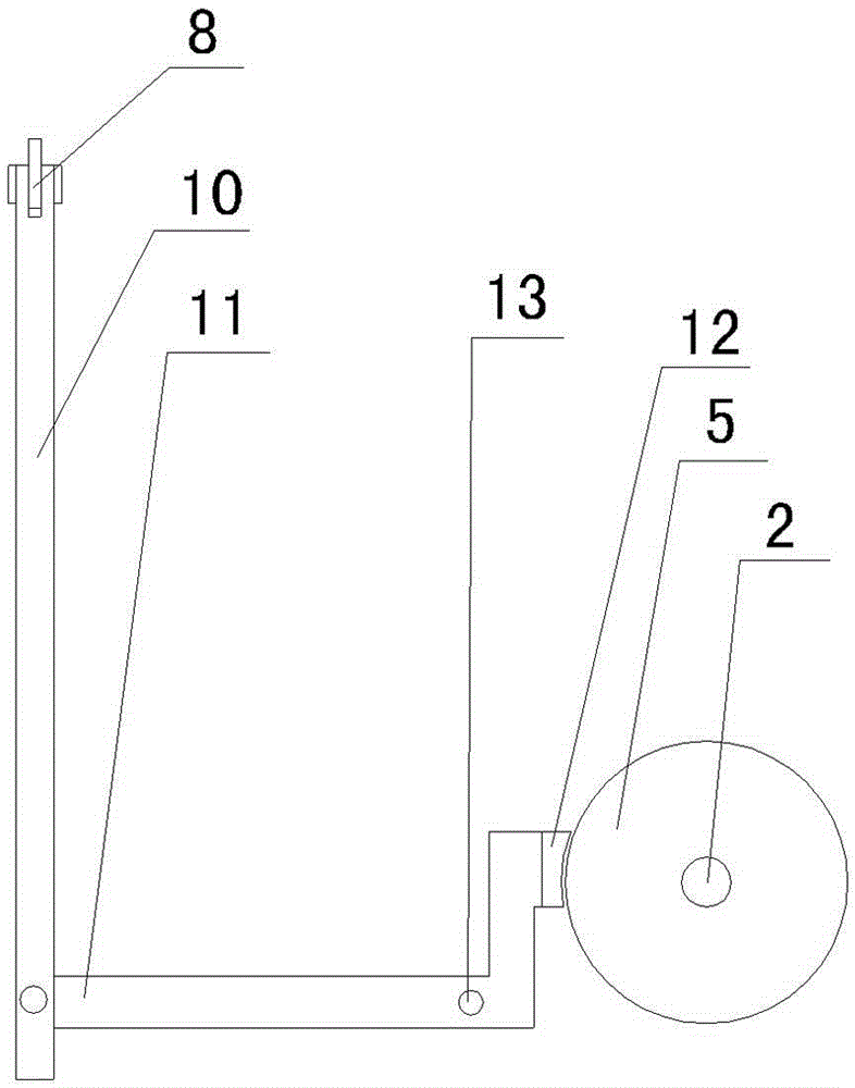
[0010] See figure 1 , figure 2 As shown, a copper wire feeding device includes a frame 1, a reel fixed shaft 2 and a roller 4 corresponding to the reel 3 are arranged on the frame 1, and a guide is installed on the upper end of the corresponding roller 4 on the frame. Runner, brake disc 5 is installed on one side of the fixed shaft 2 of the reel, the guide runner includes a fixed runner 6 and a movable runner 7, and the outer edge of the fixed runner 6 has at least two annular grooves, preferably a fixed runner 6 has four annular grooves, and the movable runner 7 has three annular grooves, so that the copper wire can be wound three times to reduce the pressure of the copper wire hanging the movable runner 7. The fixed runner 6 is installed on the upper end of the frame 1, and the movable The runner 7 is installed on one end of the support rod 8, the support rod 8 is installed on the frame 1 through the first rotating shaft 9, the other end of the support rod 8 is hingedly co...


PUM


Abstract

The invention relates to the technical field of copper wire machining, in particular to a copper wire feeding device. By means of the copper wire feeding device, a reel can stop rotating automatically when wire breaking occurs while feeding is conveniently achieved, and copper wire winding and the like are effectively prevented. The copper wire feeding device comprises a rack provided with a reel fixing shaft and a roller corresponding to the reel, and guide runners are installed at the positions, corresponding to the upper end of the roller, of the rack. The copper wire feeding device is characterized in that a brake disc is installed on one side of the reel fixing shaft, the guide runners comprise the fixed runner and the movable runner, the outer edge of the fixed runner is at least provided with two annular grooves, and the fixed runner is installed at the upper end of the rack; the movable runner is installed at one end of a supporting rod, the supporting rod is installed on the rack through a first rotating shaft, and the other end of the supporting rod is hinged to the upper end of a vertical connecting rod; and the lower end of the vertical connecting rod is hinged to one end of a transverse connecting rod, the other end of the transverse connecting rod is provided with a brake sheet matched with the brake disc, and the transverse connecting rod is installed on the rack through a second rotating shaft.

Description

technical field [0001] The invention relates to the technical field of wire processing, in particular to a copper wire feeding device. Background technique [0002] Wire is an essential component in electrical equipment. Generally, the wire is wrapped with an insulating plastic layer on the outside of the inner copper core. In the wire production process, the inner copper core is processed separately first, and then passed through another process. The insulating plastic layer is processed on the outside of the copper core. The inner copper core is generally formed of copper wire. After being processed separately, it will be wound on the reel. When processing is required, the reel is placed on the shelf, and then the copper wire is pulled for loading. , because the copper wire material is conveyed backward by pulling the copper wire by pulling force, sometimes the wire breakage will occur during the pulling and feeding process. . Contents of the invention [0003] In orde...

Claims


Application Information

Patent Timeline
IPC IPC(8): B65H54/02B65H57/14B65H63/024
Inventor 高士红
Owner WUXI VIGOROUS ELECTRIC
Why Eureka
Try Eureka