Vacuum pump blade and manufacturing method and device

A technology for manufacturing equipment and vacuum pumps, applied in the direction of mechanical equipment, pumps, pump components, etc., can solve the problems of ineffective weight reduction, cost increase, and performance degradation, and achieve shear strength, increase performance strength, The effect of increasing structural strength

Active Publication Date: 2017-05-24
世特科流体动力系统(常州)有限公司
View PDF7 Cites 0 Cited by
  • Summary
  • Abstract
  • Description
  • Claims
  • Application Information

AI Technical Summary

Problems solved by technology

In this way, the weight reduction effect cannot be effectively achieved, resulting in an increase in cost and a decrease in performance.

Method used


Image

  • Vacuum pump blade and manufacturing method and device
  • Vacuum pump blade and manufacturing method and device
  • Vacuum pump blade and manufacturing method and device

Examples


Embodiment Construction

[0032] In order to make the object, technical solution and advantages of the present invention clearer, the present invention will be further described in detail below in conjunction with the accompanying drawings and embodiments. It should be noted that the drawings are only illustrative and not drawn to a strict scale, and there may be partial enlargements and reductions for the convenience of description, and there may be certain omissions for some known structures.

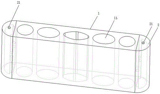
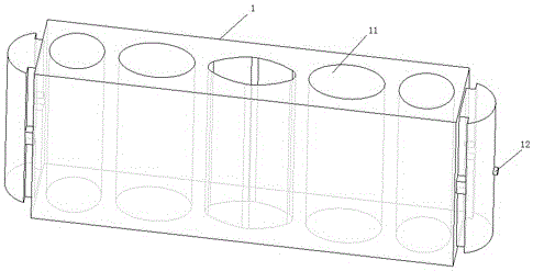
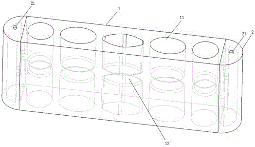
[0033] see figure 1 with figure 2 , the present invention provides an embodiment of the vane structure of a vacuum pump, which includes a vane body 1 and wear-resistant end portions 2 that are mated and connected to both ends of the vane body. The middle part of the blade body 1 is provided with a plurality of lightening holes 11 which are elliptical from the center and gradually become circular to both sides, and a first injection point 12 is provided at the center of one end of the blade body 1 . A second...


PUM


Abstract

The invention provides a vacuum pump blade and a manufacturing method and device. The blade comprises a blade body and two end abrasion resisting end portions connected with the blade body. A plurality of lightening holes are formed in the middle part of the blade body, wherein the lightening holes are oval in center and gradually become circular towards the two sides. A first injection molding point is arranged at the center position of each end of the blade body, a second injection molding point is arranged at the center position of one end of each abrasion resisting end portion, and the plane where the first injection molding points are located is perpendicular to the plane where the second injection molding points are located. The positions of the injection molding points of a middle high-strength structure part of the vacuum pump blade are adjusted to the side edge positions from the middle positions, so that distribution of glass fiber in components is better facilitated, the component shearing strength is improved, and the performance strength is improved. In addition, the shape of the lightening holes in the middle part of the blade body is designed into the shape that the lightening holes are oval in center and gradually become circular towards the two sides, and the strength performance can be improved under the situation that the lightening effect is achieved.

Description

technical field [0001] The invention relates to the field of automobile vacuum pumps, in particular to a vacuum pump blade, a manufacturing method and equipment. Background technique [0002] For the integral vacuum pump blades currently on the market, the middle part of the high-strength material, the position of the injection point is generally in the middle, the middle of the bottom or the middle of the end face. During the injection molding filling process, the glass fiber material will form a section in the middle position, resulting in lower performance strength in the middle position. [0003] In addition, the weight-reducing holes of high-strength materials in the middle of vacuum pump blades are generally regular circles, squares, triangles, etc. In this way, the weight reduction effect cannot be effectively achieved, resulting in an increase in cost and a decrease in performance. At the same time, during the working process of the blade, the main way of bearing f...

Claims


Application Information

Patent Timeline
IPC IPC(8): F04C29/00F04C25/02B29C45/26B29B11/08B29K71/00B29L31/08
CPCB29B11/08B29C45/26B29K2071/00B29L2031/082F04C25/02F04C29/00F04C2240/20
Inventor 秦杰王文平柳松
Owner 世特科流体动力系统(常州)有限公司
Why Eureka
Try Eureka