Electric energy metering box protector
A protective device and metering box technology, which is applied in the direction of measuring devices, measuring electrical variables, measuring time integration, etc., can solve problems such as easy deformation, instrument damage, instrument open circuit failure, etc., and achieve the effect of reducing impact and damage
- Summary
- Abstract
- Description
- Claims
- Application Information
AI Technical Summary
Problems solved by technology
Method used
Image
Examples
Embodiment 1
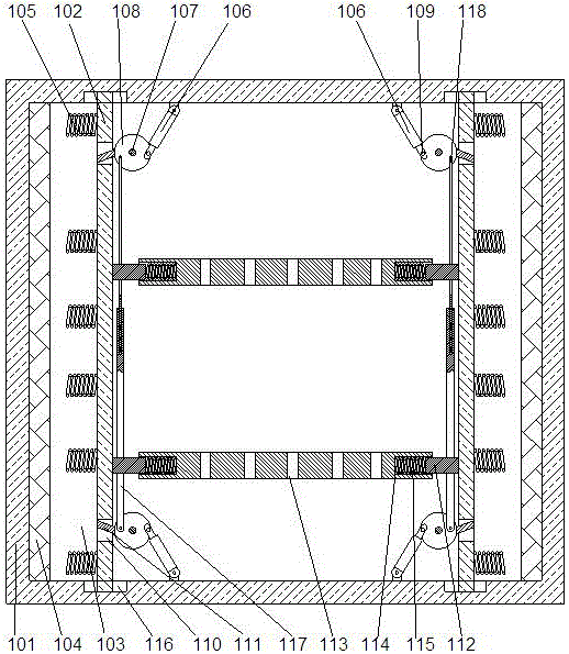
[0022] In this embodiment, in order to conveniently control the rotation angle of the bushing, preferably, a channel 110 corresponding to the position of the support rod 107 is provided on the partition 102, and the length direction of the channel is perpendicular to The plane where the bottom of the box body is located is provided with bayonet pin 111 on the outer wall of the sleeve 108, so that one end of the bayonet pin is fixedly connected on the sleeve pipe and can be welded on the sleeve pipe, and the other end is a free end, so that the When the sleeve 108 rotates around the support rod 107 , the bayonet pin 111 can be embedded in the inside of the through slot 110 . When the partition moves to the inside of the box under the action of external force, the support rod on the partition moves synchronously. Since the sleeve on the support rod is connected with the cylinder, when the support rod moves, under the action of the cylinder, the sleeve Rotate around the support r...
Embodiment 2
[0025]In this embodiment, in order to facilitate the installation of the meter, preferably, a support plate 112 is provided on the end surface of the partition 102 away from the protective pad 104, so that the support plate is parallel to the end surface of the bottom of the box body. Plane, the support plate 112 is at least 2 arranged at intervals along the height direction of the partition 102, and a mounting plate 113 for installing an electric meter is arranged between the 2 partitions 102, so that the mounting plate is Detachable connection, mounting holes for installing instruments can be set on the mounting plate, the mounting plate 113 is parallel to the bottom end surface of the box body 101, and slots 114 are respectively provided at both ends of the mounting plate 113 , the support boards 112 are respectively plugged into the corresponding slots 114 on the installation board 113 . When the support plate is inserted inside the slot, the installation plate can slide r...
Embodiment 3
[0028] In this embodiment, in order to automatically reset the sleeve after rotation, preferably, a pull-down rod 117 is provided on the lower sleeve 108, so that the lower end of the pull-down rod 117 is rotatably connected to the On the sleeve 108, when the sleeve is relatively rotated, the pull-down rod moves horizontally under the drive of the sleeve. The end of the pull-down rod 117 away from the sleeve 108 is a hollow structure. The sleeve 108 is provided with an upper pull rod 118, so that the upper pull rod 118 is rotatably connected to the sleeve 108. When the sleeve rotates relatively, it drives the upper pull rod to move horizontally synchronously, and the described upper pull rod The lower end of 118 is inserted inside the upper end of the pull-down rod 117, and a high-strength spring is arranged at the bottom of the pull-down rod 118, so that the upper end of the high-strength spring is fixedly connected to the pull-up rod, and the high-strength spring is far away ...
PUM
 Abstract
Description
Claims
Application Information
 - R&D
- Intellectual Property
- Life Sciences
- Materials
- Tech Scout
- Unparalleled Data Quality
- Higher Quality Content
- 60% Fewer Hallucinations
Browse by: Latest US Patents, China's latest patents, Technical Efficacy Thesaurus, Application Domain, Technology Topic, Popular Technical Reports.
© 2025 PatSnap. All rights reserved.Legal|Privacy policy|Modern Slavery Act Transparency Statement|Sitemap|About US| Contact US: help@patsnap.com

