Directional control force arm and virtual reality experience device

A technology of direction control and force arm, which is applied in the direction of program control manipulators, claw arms, manufacturing tools, etc., which can solve problems such as poor experience effect, many blanks in the industry, and people being thrown out.

Pending Publication Date: 2017-05-31
重庆梦神科技有限公司
View PDF19 Cites 4 Cited by
  • Summary
  • Abstract
  • Description
  • Claims
  • Application Information

AI Technical Summary

Problems solved by technology

[0003] As we all know, the virtual reality experience is in the early stage of development, and many needs have not been effectively resolved, and there are many gaps in the industry. Most of the business units are using highly similar dynamic seat systems. Simple, very sh

Method used


Image

  • Directional control force arm and virtual reality experience device
  • Directional control force arm and virtual reality experience device
  • Directional control force arm and virtual reality experience device

Examples


Embodiment 1

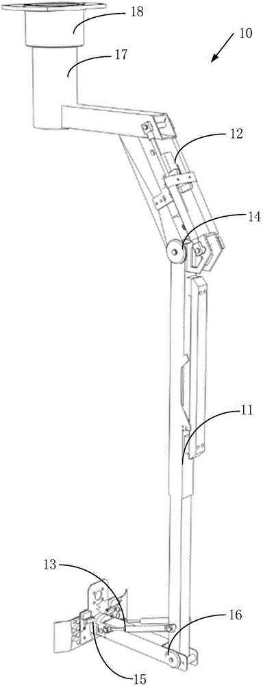
[0059] This embodiment provides a direction control moment arm 10 , including a moment arm body 11 , a first connecting portion 12 and a second connecting portion 13 . The first connecting portion 12 and the second connecting portion 13 are respectively disposed at two ends of the arm body 11 . The arm body 11 is rod-shaped.

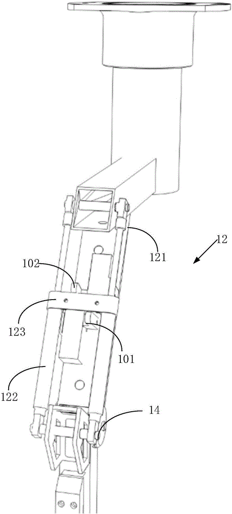
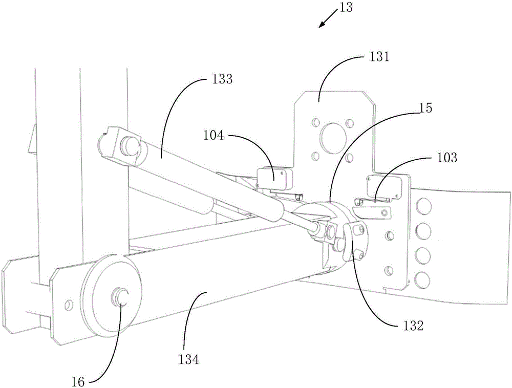
[0060] The first connecting portion 12 and the second connecting portion 13 are pivotally connected to the arm body 11 respectively, the first rotating shaft 14 connecting the first connecting portion 12 and the arm body 11 is connected to the second connecting portion 13 and the arm body 11 The second rotating shafts 15 are all in the horizontal direction and perpendicular to each other.

[0061] A first sensor 101 and a second sensor 102 are disposed on the first connecting portion 12 . When the first connecting part 12 rotates relative to the arm body 11 , the first sensor 101 or the second sensor 102 senses the rotation signal.

[0062] A third se...

Embodiment 2

[0090] This embodiment provides a virtual reality experience device 1 , including a controller 20 and a display 30 electrically connected to each other, and also includes the direction control arm 10 in Embodiment 1.

[0091] The first sensor 101, the second sensor 102, the third sensor 103 and the fourth sensor 104 in the direction control arm 10 are respectively electrically connected to the controller 20, and the sensed signals are respectively fed back to the controller 20, and the controller 20 controls the display 30 to display corresponding images.

[0092] Specifically, when the first sensor 101 senses the forward movement, the controller 20 controls the display 30 to display the forward movement, and when the second sensor 102 senses the backward movement, the controller 20 controls the display 30 to display the backward movement. When the third sensor 103 senses the right movement, the controller 20 controls the display 30 to display the right movement, and when the ...


PUM


Abstract

The invention provides a directional control force arm. The directional control force arm comprises a force arm body, a first connecting part and a second connecting part; the first connecting part and the second connecting part are installed at the two ends of the force arm body which is in a rod shape correspondingly and connected to the force arm body in a pivotal rotating mode correspondingly, a first sensor and a second sensor are installed on the first connecting part, and when the first connecting part rotates relative to the force arm body, a rotating signal is sensed by the first sensor or the second sensor; and a third sensor and a fourth sensor are installed on the second connecting part, and when the second connecting part rotates relative to the force arm body, a rotating signal is sensed by the third sensor or the fourth sensor. The invention further provides the virtual reality experience device. According to the directional control force arm and the virtual reality experience device, virtual reality experience can be conducted through standing, and more diversified and freer man-machine interaction and dynamic modes are achieved.

Description

technical field [0001] The invention relates to the field of virtual reality equipment, in particular to a direction control arm and a virtual reality experience equipment. Background technique [0002] Virtual reality technology is a computer simulation system that can create and experience a virtual world. It uses a computer to generate a simulated environment, which is an interactive three-dimensional dynamic scene and a system simulation of entity behavior that integrates multi-source information, allowing users to immerse themselves in the virtual world. Environment. [0003] As we all know, the virtual reality experience is in the early stage of development, and many needs have not been effectively resolved, and there are many gaps in the industry. Most of the business units are using highly similar dynamic seat systems. Simple, the product life cycle is very short. [0004] Most of the existing virtual reality experience devices are experienced by sitting in the cab...

Claims


Application Information

Patent Timeline
IPC IPC(8): B25J9/00B25J17/00B25J9/16B25J18/02
CPCB25J9/00B25J9/1694B25J17/00B25J18/02
Inventor 冯博
Owner 重庆梦神科技有限公司
Why Eureka
Try Eureka