Multi-row gas pipe

A technology for exhaust pipes and air pipes, which is applied in the direction of hoses, pipes, pipes/pipe joints/pipe fittings, etc., to achieve the effect of high degree of freedom and easy storage

Inactive Publication Date: 2017-05-31
SHENZHENJTK WIRE&CABLE CO LTD
View PDF6 Cites 0 Cited by
  • Summary
  • Abstract
  • Description
  • Claims
  • Application Information

AI Technical Summary

Problems solved by technology

[0004] In view of the shortcomings of the above-mentioned prior art, the purpose of the present invention is to provide a multi-exhaust pipe, aiming at solving the defect of the prior art that there is no cable integration for cylinder intake and exhaust functions

Method used


Image

  • Multi-row gas pipe
  • Multi-row gas pipe

Examples


Embodiment Construction

[0015] The present invention provides a multi-exhaust pipe. In order to make the purpose, technical solution and effect of the present invention clearer and clearer, the present invention will be further described in detail below with reference to the accompanying drawings and examples. It should be understood that the specific embodiments described here are only used to explain the present invention, not to limit the present invention.

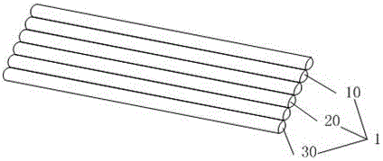
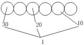
[0016] Please also refer to figure 1 and figure 2 ,in figure 1 It is a structural schematic diagram of a preferred embodiment of the multi-exhaust pipe in the present invention, figure 2 It is a side view of a preferred embodiment of the multiple exhaust pipes of the present invention. The multi-exhaust pipe 1 includes a plurality of air pipes 10 arranged in parallel for transporting gas; the plurality of air pipes at least include an air inlet pipe 20 and an air outlet pipe 30 .

[0017] When the present invention is actually implement...


PUM


Abstract

The invention provides a multi-row gas pipe. The multi-row gas pipe comprises a plurality of parallel gas pipes used for transmitting gas, the multiple gas pipes at least comprise a gas inlet pipe and a gas outlet pipe, and due to the fact that the multiple gas pipes with the gas transmitting function are arranged in parallel, the gas pipe function is integrated in winding displacement; the multi-row gas pipe adopting the multiple gas pipes is more easily stored, and when the multi-row gas pipe is applied to air cylinder transmission, the freedom degree is higher.

Description

technical field [0001] The invention relates to the technical field of air pipes, in particular to a multi-exhaust pipe. Background technique [0002] At present, the trachea is single. In actual use, it is often necessary to use multiple pipes at the same time, which causes troubles for installation, and is not neat and beautiful. [0003] Therefore, the prior art still needs to be improved and developed. Contents of the invention [0004] In view of the disadvantages of the above-mentioned prior art, the object of the present invention is to provide a multi-exhaust pipe, aiming at solving the defect in the prior art of integrating air intake and exhaust functions of cylinders without cables. [0005] In order to achieve the above object, the present invention has taken the following technical solutions: [0006] A multi-exhaust pipe, including a plurality of air pipes arranged in parallel for transporting gas; the plurality of air pipes at least include an air inlet pi...

Claims


Application Information

Patent Timeline
Patent Type & Authority Applications(China)
IPC IPC(8): F16L11/04F16L11/12
CPCF16L11/04F16L11/12F16L11/121
Inventor 张海斌
Owner SHENZHENJTK WIRE&CABLE CO LTD
Why Eureka
Try Eureka