
Testing device and display panel

A test device and display panel technology, applied to static indicators, instruments, etc., can solve problems such as poor display, low level of signal line, affecting display effect, etc., to achieve the effect of avoiding poor display and improving display effect

Pending Publication Date: 2017-05-31
HEFEI XINSHENG OPTOELECTRONICS TECH CO LTD +1
View PDF6 Cites 0 Cited by
  • Summary
  • Abstract
  • Description
  • Claims
  • Application Information

AI Technical Summary

Problems solved by technology

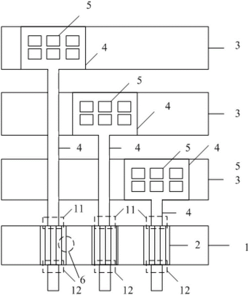
Among them, the connection position 6 between the Switch switch and the control switch line is the position where static electricity often occurs. When ElectroStatic discharge (ESD) occurs at this position, the signal line and the control switch line will be short-circuited, because the control switch line will eventually be connected to the A low level, so t

Method used


Image

  • Testing device and display panel
  • Testing device and display panel
  • Testing device and display panel

Examples


Example Embodiment

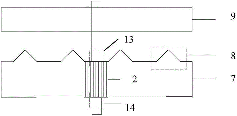
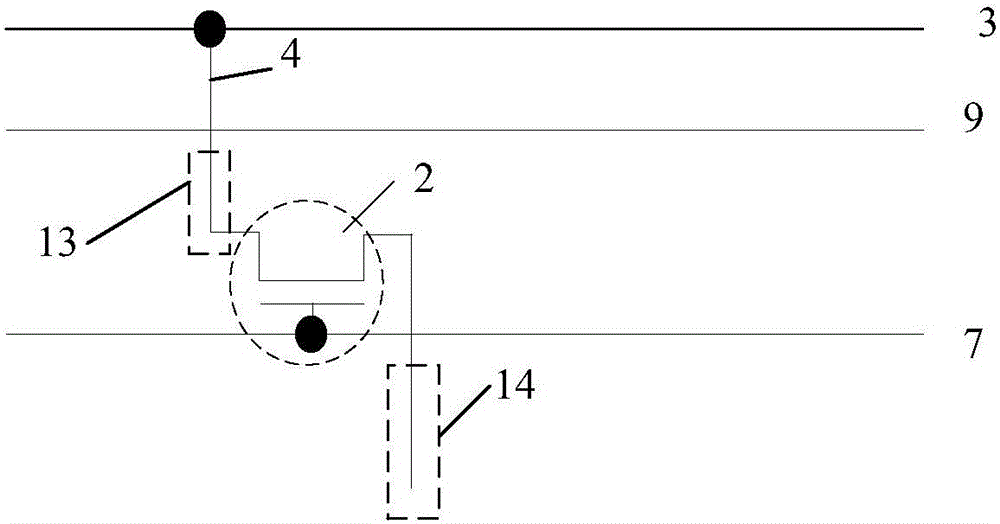
[0028] A test device provided by the embodiment of the present application, such as figure 2 As shown, it includes a control switch line 7 and at least one control switch 2 arranged on the control switch line 7. The test device also includes a signal input end 14 and a signal output end 13 for testing the control signal. Under the control of the control switch line 7, the signal input end 14 and the signal output end 13 are turned on or off, the control switch line 7 is provided with a discharge tip 8, and the device further comprises: The conducting wire 9 disposed opposite and adjacent to the control switch wire is used to receive the static electricity discharged from the control switch wire through the discharge tip. In a test device provided by an embodiment of the present application, a discharge tip is provided on the control switch wire, and a wire opposite to the discharge tip and adjacent to the control switch wire is provided, when the control switch When there is...


PUM


Abstract

An embodiment of the invention provides a testing device and a display panel with an aim to avoid short circuit occurring to a signal line and a control switch line, avoid poor display caused and improve display effect. The testing device comprises the control switch lie and at least one control switch arranged on the control switch line, the testing device further comprises a signal input end and a signal output end which are used for testing control signals, the control switches enable the signal input end and the signal output end to be connected or disconnected under control of the control switch line, and a discharge tip is further arranged on the control switch line; the testing device further comprises a lead opposite to the discharge tip and neighboring to the control switch line and used for receiving static electricity released through the discharge tip on the control switch line.

Description

technical field [0001] The present application relates to the field of display technology, in particular to a testing device and a display panel. Background technique [0002] A Liquid Crystal Display (LCD) has the advantages of light weight, thin thickness, and low power consumption, and is widely used in electronic products such as televisions, mobile phones, and monitors. But in the LCD process, there is a problem of static electricity. The structure of the test (Test) part of the existing conventional products is as follows figure 1 As shown, it mainly includes the control switch line 1, the control switch (Switch switch) 2, and the signal output terminal 11 and the signal input terminal 12 of the test control signal. The signal output terminal is connected to the signal line 3 (Gate or Data) through the connection line 4 , the signal line 3 is connected to the connection line 4 through the via hole 5, the Switch switch 2 is a thin film transistor (ThinFilm Transistor,...

Claims


Application Information

Patent Timeline
IPC IPC(8): G09G3/00
CPCG09G3/006
Inventor 王国磊
Owner HEFEI XINSHENG OPTOELECTRONICS TECH CO LTD
Learn More