Air purification device

A technology of air purification device and purifier, which is applied in the direction of coupling device, parts of connection device, electrical components, etc., which can solve the problems of purifier operation influence, instability, loose plug, etc., and improve the stability of plug power supply , Improving the stability of plugging and preventing loosening of plugging

Active Publication Date: 2017-05-31
QUANZHOU QUANGANG JIACHENG INFORMATION TECH CO LTD
View PDF4 Cites 23 Cited by
  • Summary
  • Abstract
  • Description
  • Claims
  • Application Information

AI Technical Summary

Problems solved by technology

[0002] Indoor pollution has become an important threat to people's healthy home life. In order to create a good home environment, many people have installed air purifiers indoors. The existing air purifiers are powered by plugging. The instability of plugging, the risk of electric shock caused by electric arc is easy to be generated during the plugging process, which has great disadvantages. In order to avoid the occurrence of safety accidents, emergency treatment devices should be added during use to increase the safety of power supply, and at the same time The electrical connection lines of the existing air purifiers are generally set longer, and are easily affected by external factors such as dragging and pulling, which may cause loose plug connections and lead to poor contact, which will affect the normal operation of the purifier.

Method used


Image

  • Air purification device
  • Air purification device
  • Air purification device

Examples


Embodiment Construction

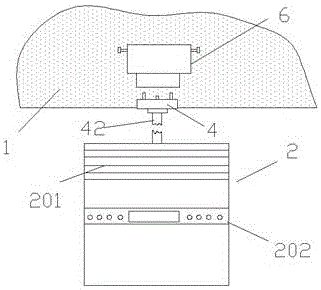
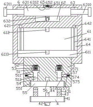
[0023] Such as Figure 1-Figure 8 As shown, an air purification device of the present invention includes a wall 1 and a purifier 2 arranged below the wall 1. A control part 202 is provided at the center of the front end of the purifier 2, and a control part 202 above the control part 202 The front end of the purifier 2 is provided with an atomization port 201, the front end of the wall 1 is fixed with a power distribution seat 6, and the bottom of the power distribution seat 6 is provided with an electrical connector 4, and the electrical connector 4 The bottom is provided with a wire 42 connected to the rear side of the purifier 2, and the inner bottom of the power distribution seat 6 is provided with an empty groove 61, and the left and right sides of the empty groove 61 are provided with sliding joint grooves 64. A screw-shaped rod 641 is provided in the sliding connection groove 64, and the top of the screw-shaped rod 641 is connected to the electric rotating machine 642. ...


PUM


Abstract

The invention discloses an air purification device, which comprises a wall body and a purifier arranged under the wall body, wherein a regulation and control part is arranged in the center of the front end surface of the purifier; an atomization opening is formed in the front end surface of the purifier arranged above the regulation and control part; a power distribution seat is fixedly arranged at the front end surface of the wall body; an electric connection head is arranged at the bottom of the power distribution seat; the bottom of the electric connection head is provided with a conducting wire connected with the back side surface of the purifier; a hollow groove is formed in the inner bottom of the power distribution seat; slide connection grooves are respectively formed in the two sides of the hollow groove; screw rods are arranged in the slide connection grooves; the tops of the screw rods are connected with an electric rotating machine; a slide connection plate is arranged in the hollow groove; the two side ends of the slide connection plate penetrates through the slide connection groove and is connected with the screw rods in a matched way through screw threads; the bottom of the slide connection plate is provided with an assembly block; the bottom of the assembly block penetrates through the bottom wall of the power distribution seat and is in slide matched connection with the power distribution seat; first pushing cavities are correspondingly arranged at the left side and the right side inside the assembly block. The air purification device has the advantages that the structure is simple; the operation is convenient; the automatic insertion connection power supply is realized; the safety is high.

Description

technical field [0001] The invention relates to the technical field of air purification, in particular to an air purification device. Background technique [0002] Indoor pollution has become an important threat to people's healthy home life. In order to create a good home environment, many people have installed air purifiers indoors. The existing air purifiers are powered by plugging. The instability of plugging, the risk of electric shock caused by electric arc is easy to be generated during the plugging process, which has great disadvantages. In order to avoid the occurrence of safety accidents, emergency treatment devices should be added during use to increase the safety of power supply, and at the same time The electrical connection lines of the existing air purifiers are generally set longer, and are easily affected by external factors such as dragging and pulling, which may cause loose plugging and lead to poor contact, which will affect the normal operation of the pu...

Claims


Application Information

Patent Timeline
Patent Type & Authority Applications(China)
IPC IPC(8): H01R13/629H01R13/631H01R13/633H01R13/639F24F3/16
CPCF24F3/16H01R13/629H01R13/631H01R13/633H01R13/639H01R13/6395
Inventor 李彬
Owner QUANZHOU QUANGANG JIACHENG INFORMATION TECH CO LTD
Why Eureka
Try Eureka