Furniture hinge

A furniture and hinge technology, applied in the field of furniture hinges, can solve the problems of small joint surface and low installation height of the cover plate, and achieve the effect of easy access

Active Publication Date: 2017-05-31
土耳其萨麦提模子及矿物工商股份公司
View PDF10 Cites 2 Cited by
  • Summary
  • Abstract
  • Description
  • Claims
  • Application Information

AI Technical Summary

Problems solved by technology

A possible problem here is that due to the low mounting height of the cover plate there is a small engagement surface on which to exert the force required for manually moving the cover plate and for rotating the two pins

Method used


Image

  • Furniture hinge
  • Furniture hinge
  • Furniture hinge

Examples


Embodiment Construction

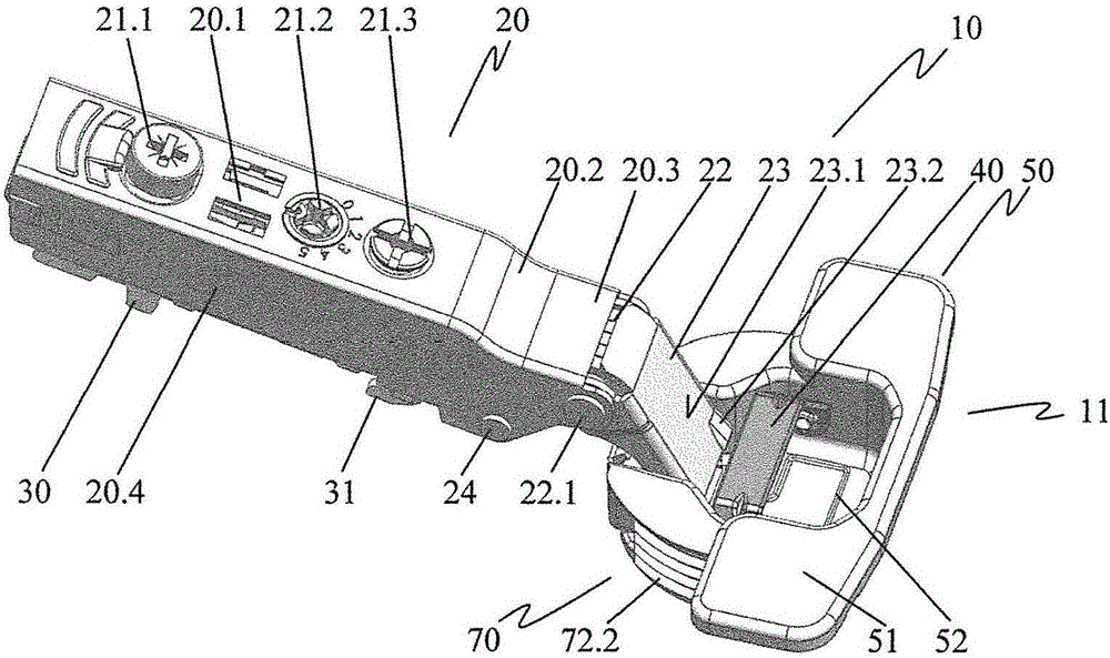
[0030] figure 1 The furniture hinge 10 is shown in a front perspective view in a first position of the actuating element 40 of the raised arrangement.

[0031]A hinge arm 20 and a stop 11 are associated with the furniture hinge 10 . The hinge arm 20 is connected to the stop 11 via a joint. Along the rear span 20.1 of the hinged arm 20 are arranged a depth adjustment screw 21.1, a positioner 21.2 and a support adjustment screw 21.3. The side legs 20.4 are connected to the rear span 20.1 on both sides. The hinge arm 20 is engaged in a connecting piece 30 comprising a connecting hook 31 . Towards the joint, the rear crotch 20.1 transitions via a transition section 20.2 into a section 20.3 which is concave relative to the rear crotch 20.1. The female section 20.3 is connected via the outer articulation 22 to the outer hinge lever 23, which comprises an actuation surface 23.1 with a protrusion 23.2 oriented towards the hinge cup 52 with the actuation piece 40. The outer articu...


PUM


Abstract

The invention relates to a furniture hinge (10) with a stop (11) which is paired with a hinge cup element (50) comprising a hinge cup (52) and with at least one securing element, in particular a clamping jaw (72.1, 72.2) of a spreading element (72) or a securing pin (84.1, 84.2), for securing the stop on a piece of furniture. The furniture hinge also comprises at least one actuating element (40, 80.1, 80.2), which is operatively connected to the securing element, and a hinge arm (20), which is connected to the hinge cup element in a foldable manner via a joint connection. According to the invention, the at least one actuating element is arranged in the movement direction of the hinge arm so as to be moved from a first position to a second position by the hinge arm when the hinge arm is folded into the hinge cup. The furniture hinge can be assembled onto a piece of furniture without additional tools.

Description

technical field [0001] The invention relates to a furniture hinge with a stop associated with a hinge cup having a hinge cup and at least one fastener for fastening a stop on a piece of furniture, in particular an extension A jaw or fastening pin is associated with at least one manipulator operatively connected to the fastener and with a hinge arm foldably connected to the hinge cup via an articulation. Background technique [0002] Such a furniture hinge is known from publication EP 1643061 A1. Furniture hinges are fastened in holes in a piece of furniture using hinge cups. Arrange the flange side towards the hinge cup. Two bolts are mounted rotatably on a flange lateral to the hinge cup. The one-sided support of the bolt makes the anchoring rib arranged obliquely and protruding toward the side of the hinge cup extend into the hole of the furniture. The axis of rotation of the bolt lies in the direction of the longitudinal axis of the hole. Outside the hole, each bolt ...

Claims


Application Information

Patent Timeline
Patent Type & Authority Applications(China)
IPC IPC(8): E05D5/08
CPCE05Y2600/52E05Y2900/20E05D5/08E05D3/12
Inventor 阿图尔·希尔齐费尔贝恩德·勒德
Owner 土耳其萨麦提模子及矿物工商股份公司
Why Eureka
Try Eureka