Particle material drying robot

A technology of granular materials and robots, applied in the field of mechanical processing, can solve the problems of increased energy consumption, low drying efficiency, and inability to achieve rapid unloading and quantitative heating, and achieve the effect of enhancing stability and ensuring drying.

Inactive Publication Date: 2017-06-06
ZHONGZHOU UNIV
View PDF6 Cites 10 Cited by
  • Summary
  • Abstract
  • Description
  • Claims
  • Application Information

AI Technical Summary

Problems solved by technology

The beneficial effect of this utility model is that, since the material continuously rolls along with the rotation of the drum during the drying process, the heat generated by the far-infrared heating element acts directly on the material in the drum, and the material is heated evenly Under the action of the heating chamber, a negative pressure is formed in the heating chamber, and the moisture generated during the drying process can be efficiently discharged from the heating chamber. Therefore, the material drying device of the present invention has high thermal efficiency and is not only suitable for drying granular materials. , and is also suitable for coating and moisture-proof treatment of granules, pills, and tablets; however, the heat is not recycled, resulting in increased energy consumption, and because of the drum design, it is not possible to achieve rapid feeding and quantification heating
[0004] A drying device is disclosed in the authorized announcement number 205536973U, especially a plastic particle dryer; the technical solution adopted by the utility model is: an improved solid particle material dryer, including a drying box and a supporting drying box The bracket of the body, the upper part of one side of the drying box is provided with a feed port, and the bottom is provided with a discharge port. An inclined filter screen is installed above the drying box. The discharge pipe outside the box, the outside of the drying box is provided with a fan, the air outlet of the fan is connected to the heater through the air pipe, and the heater is connected to the bottom of the drying box, and the air outlet of the drying box is connected to the bottom of the drying box The top is connected with an exhaust pipe, the exhaust pipe is connected with a cyclone separator, and the cyclone separator is connected with a bag filter, and the upper air duct of the bag filter is connected with the air inlet of the fan; although the drying effect is obtained, it is not suitable for It cannot effectively control the drying degree of protein materials; however, it still does not solve the phenomenon of high energy consumption and low drying efficiency

Method used


Image

  • Particle material drying robot
  • Particle material drying robot
  • Particle material drying robot

Examples


Embodiment 1

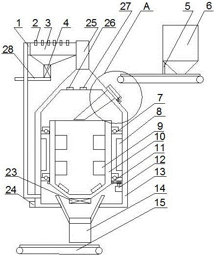
[0039] A granular material drying robot, comprising a feeding mechanism 6, a drying mechanism arranged at the rear of the feeding mechanism 6, a drying mechanism arranged on the upper part of the drying mechanism, and arranged at the rear of the drying mechanism The discharging mechanism, and the control mechanism 24 interconnected with the signal of the feeding mechanism 6, the drying mechanism, the drying mechanism and the discharging mechanism;

[0040] The feeding mechanism includes a feeding conveyor belt 64, a material bin 61 arranged above the rear of the feeding conveyor belt 64, and a material protection plate 63 arranged on both sides of the feeding conveyor belt 64, arranged on the material bin 61 Material limiting plate 5 at the lower outlet;

[0041] The drying mechanism includes a casing 13, a driving motor 12 arranged at the bottom of the casing 13, a drying drum 10 arranged at the top of the driving motor 12, and a stirring blade 9 is arranged in the drying dru...

Embodiment 2

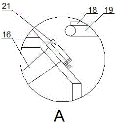
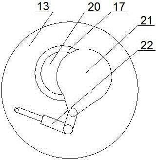
[0053] The upper part of the housing 13 is provided with a shell hole 20 matched with the feeding conveyor belt 64, and a shell cover 21 is arranged on the shell hole 20. The opening and closing of the shell cover 21 is controlled by a hydraulic mechanical arm 22, and the A sealing ring 17 is arranged on the peripheral side of the cover.

[0054] The shell hole 20 is provided for diverting the material to the diversion groove 16 in the clinker cylinder; the rotating bearing 7 is provided with a pressure sensor.

[0055] The rotary bearing used in this embodiment is a thrust bearing, which can ensure that while the mass is carried on it, a pressure sensor can be installed on it to sense the quality change in the drying drum, and the drying mechanism includes a housing, which is arranged on the The driving motor at the lower part of the housing is arranged on the drying cylinder above the driving motor, the stirring blade is arranged in the drying cylinder, and the lower part of...

Embodiment 3

[0057] A stirring roller 62 for preventing material from coagulating is arranged at the outlet of the lower part of the silo 61 , and a stirring column for increasing the stirring function is arranged on the stirring roller 62 .

[0058] The stirring blade 9 is a corrugated blade.

[0059] The outer wall of the drying cylinder 10 is fixed to the casing 13 through the rotating bearing 7 .

[0060] The control mechanism 24 is a microcomputer.

[0061] The drying mechanism adopted in this embodiment includes a drying pipeline arranged on the upper part of the housing, a temperature detection module arranged in the drying pipeline, and a drying module connected with the drying pipeline, and the drying module is arranged at the rear The return pipe connected with the shell; the temperature detection module and the humidity detection module are used to detect the change of the material in the clinker cylinder, which is used as one of the indicators to detect whether the drying is c...


PUM


Abstract

The invention provides a particle material drying robot which comprises a feeding mechanism, a stoving mechanism arranged on the rear portion of the feeding mechanism, a drying mechanism arranged on the upper portion of the drying mechanism, a discharging mechanism arranged on the rear portion of the stoving mechanism, and a control mechanism in signal connection with the feeding mechanism, the stoving mechanism, the drying mechanism and the discharging mechanism. To avoid the phenomena that in the prior art, drying efficiency is low and energy consumption is high during drying, the stoving mechanism is used for stoving materials, the feeing mechanism and the discharging mechanism are used for feeding and outputting the materials, the drying mechanism is used for rapidly recovering moisture in the materials, energy conversion and recovery are achieved while moisture is condensed and falls through a heat exchanger, and the drying effect is guaranteed while rapid drying is achieved.

Description

technical field [0001] The invention relates to the technical field of mechanical processing, in particular to a particle material drying robot. Background technique [0002] A dryer is a mechanical device that uses thermal energy to reduce the moisture content of materials and is used to dry objects. The dryer evaporates the moisture in the material by heating to obtain a solid material with a specified moisture content. The purpose of drying is to meet the needs of material use or further processing. The existing solid material dryers have simple structures and relatively single functions, which cannot meet the needs of use. In addition, in the existing material dryer, the gas after drying the material is directly discharged into the atmosphere, which will not only change the ambient temperature, pollute the environment, but also cause a certain waste of resources. Therefore, a new technical solution should be provided to solve the above problems. [0003] A granular m...

Claims


Application Information

Patent Timeline
Patent Type & Authority Applications(China)
IPC IPC(8): F26B11/08F26B23/08F26B25/00F26B3/347
CPCF26B3/347F26B11/08F26B25/002F26B2200/08Y02P70/10
Inventor 周万春赵晶晶
Owner ZHONGZHOU UNIV
Why Eureka
Try Eureka