
Gear dynamic transmission error measurement method and measurement device

A measuring device and technology of transmission error, applied in the field of measurement of gear dynamic transmission error, can solve the problems of reducing the authenticity of gear transmission accuracy test, difficult to study and control vibration and noise, and inability to truly simulate the working state between gears, etc. The effect of avoiding distractions

Active Publication Date: 2019-04-12
BEIJING UNIV OF TECH
View PDF4 Cites 0 Cited by
  • Summary
  • Abstract
  • Description
  • Claims
  • Application Information

AI Technical Summary

Problems solved by technology

Many inspections and experiments in the industry have confirmed that there is a direct relationship between vibration, noise and transmission error. It is difficult to study and control vibration and noise without transmission error testing.
Moreover, the current transmission error test system is usually carried out at low speed and no load, and the transmission system is tested as an ideal system without vibration
However, under high-speed conditions, the current transmission error test system cannot meet the accurate test requirements.
Most of the testing equipment only considers the static error under no-load conditions, and ignores the dynamic error under load conditions, which cannot truly simulate the actual working state of the gears, resulting in a reduction in the authenticity of the gear transmission accuracy test

Method used


Image

  • Gear dynamic transmission error measurement method and measurement device
  • Gear dynamic transmission error measurement method and measurement device
  • Gear dynamic transmission error measurement method and measurement device

Examples


Embodiment Construction

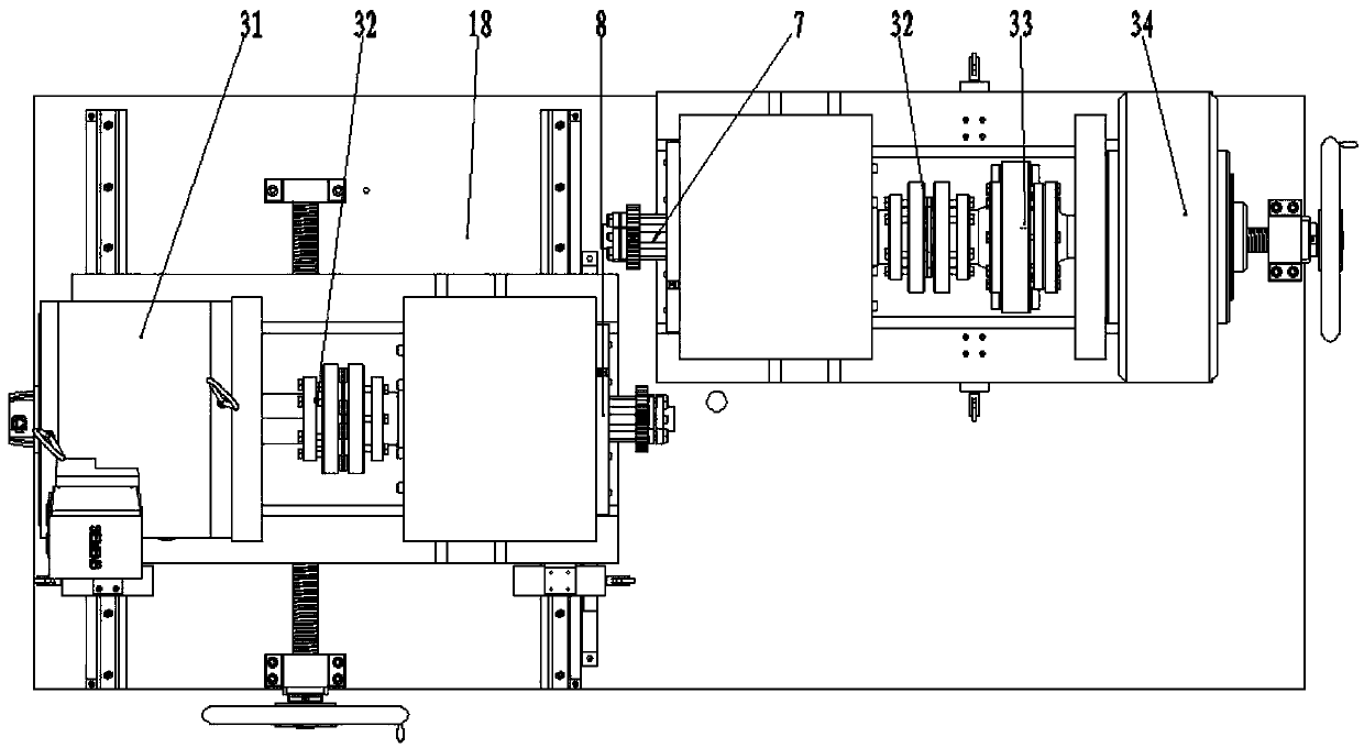
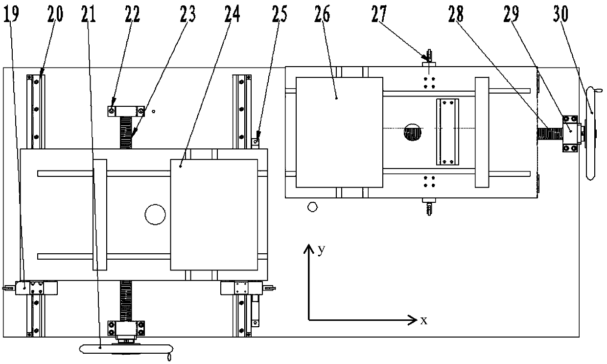
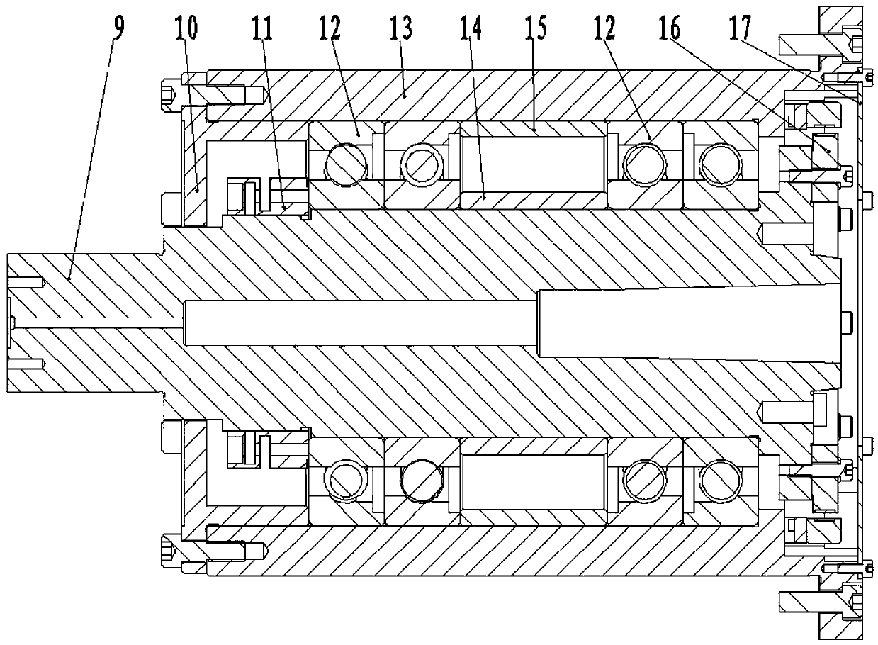
[0038] The present invention will be further described in detail below in conjunction with the accompanying drawings and specific embodiments. However, it should not be understood that the scope of the above subject matter of the present invention is limited to the following implementation manners, and all technologies realized based on the contents of the present invention belong to the scope of the present invention.

[0039] Such as Figure 4 As shown in the dynamic transmission error measurement process, the implementation steps of the gear dynamic transmission error measurement are as follows:

[0040] 1) Gear installation, ① Use the cooperation between the inner tapered surface of the short tapered shaft (4) and the tapered surface of the precision rotary shaft (8), and adjust the radial runout and end surface runout of the shaft system by means of screw adjustment. Check the installation accuracy of the short tapered shaft (4) until the runout accuracy of the shaft sys...


PUM


Abstract

The present invention relates to a gear dynamic transmission error measurement method and a gear dynamic transmission error measurement device, and belongs to the gear transmission precision measurement technology field. Aiming at the development tendency that a conventional gear measurement device is required to use the gear dynamic precision taking a gear dynamics research result as the basis to substitute for the gear static precision taking the gear geometry and kinematics research results as the basis, the present invention provides the gear dynamic transmission error measurement method and the gear dynamic transmission error measurement device. By a gear rapid assembling device, the gears of different sizes and specifications are replaced rapidly and at a high precision; by a precise movement platform, the adjustment of a center distance and the tooth width direction parameters is controlled accurately; and by utilizing a working condition simulation system to simulate the state of a gear actual working system, the measurement precision and the credibility of a dynamic transmission error are improved. By considering the gear working load and the lubrication conditions, adopting an unconnected high-precision circular grating to obtain the information of the angular positions of the driving and driven gears, and utilizing a digital phase comparison method to process the data, the gear dynamic transmission error is obtained.

Description

technical field [0001] The invention relates to a measurement method for a gear dynamic transmission error and a gear dynamic transmission error measurement device, belonging to the technical fields of gear pair transmission accuracy measurement technology, precision testing technology and instrument, and mechanical transmission technology. Background technique [0002] Gears are widely used in the transmission systems of automobiles, ships, wind power, etc., and are an important transmission part in modern industry, transportation, and energy power transmission. Due to the advantages of smooth transmission, precise transmission ratio, high efficiency and long life, gear transmission still plays an important role in power transmission and is the most widely used mechanical transmission. Due to the constraints of gear processing technology and testing technology, although my country is a big country in gear manufacturing and use, it is not a powerful country in gear manufactu...

Claims


Application Information

Patent Timeline
Patent Type & Authority Patents(China)
IPC IPC(8): G01M13/021
CPCG01M13/021
Inventor 石照耀舒赞辉李睿
Owner BEIJING UNIV OF TECH
Learn More