
A Method of Drilling 4 Holes in the Water Turbine Discharge Cone Based on Large Flow Deviated Working Conditions

A technology of discharge cone and partial working condition, which is applied in the field of drilling 4 holes in the discharge cone of hydraulic turbines based on large flow and partial working conditions, which can solve the problems of unsteady flow and pressure pulsation of hydraulic turbine units

Inactive Publication Date: 2019-04-02
哈尔滨奈格科技发展有限公司
View PDF8 Cites 0 Cited by
  • Summary
  • Abstract
  • Description
  • Claims
  • Application Information

AI Technical Summary

Problems solved by technology

[0005] The purpose of the present invention is to overcome the shortcomings and deficiencies of the prior art, and provide a method for drilling 4 holes in the discharge cone of the hydraulic turbine based on the large flow and partial working conditions, so as to solve the unsteady flow problem inside the hydraulic turbine unit, especially the vortex belt in the draft tube And the corresponding pressure pulsation problem

Method used

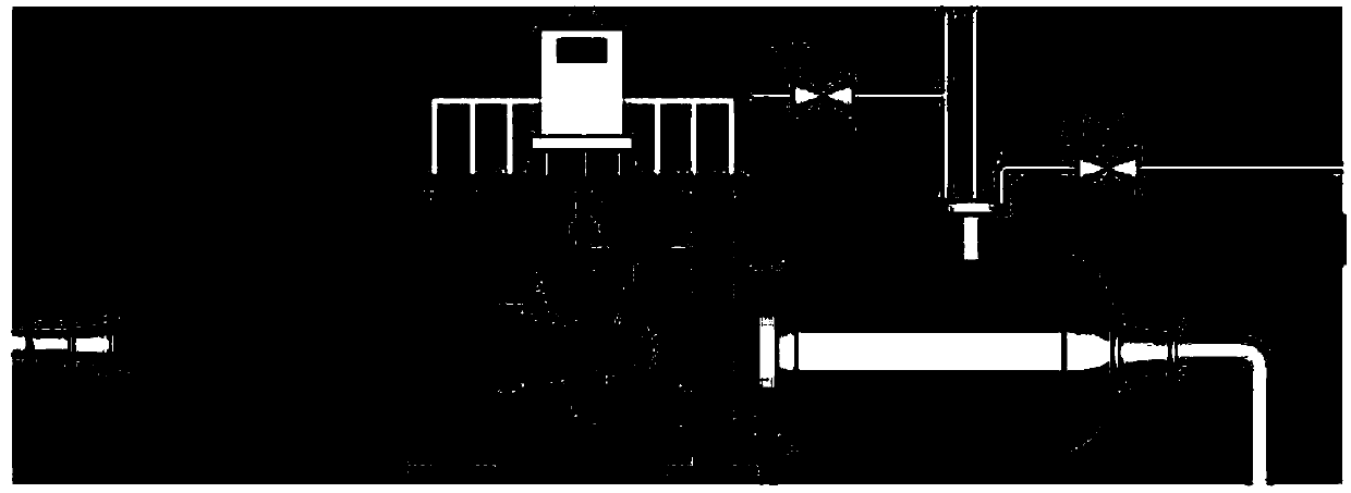
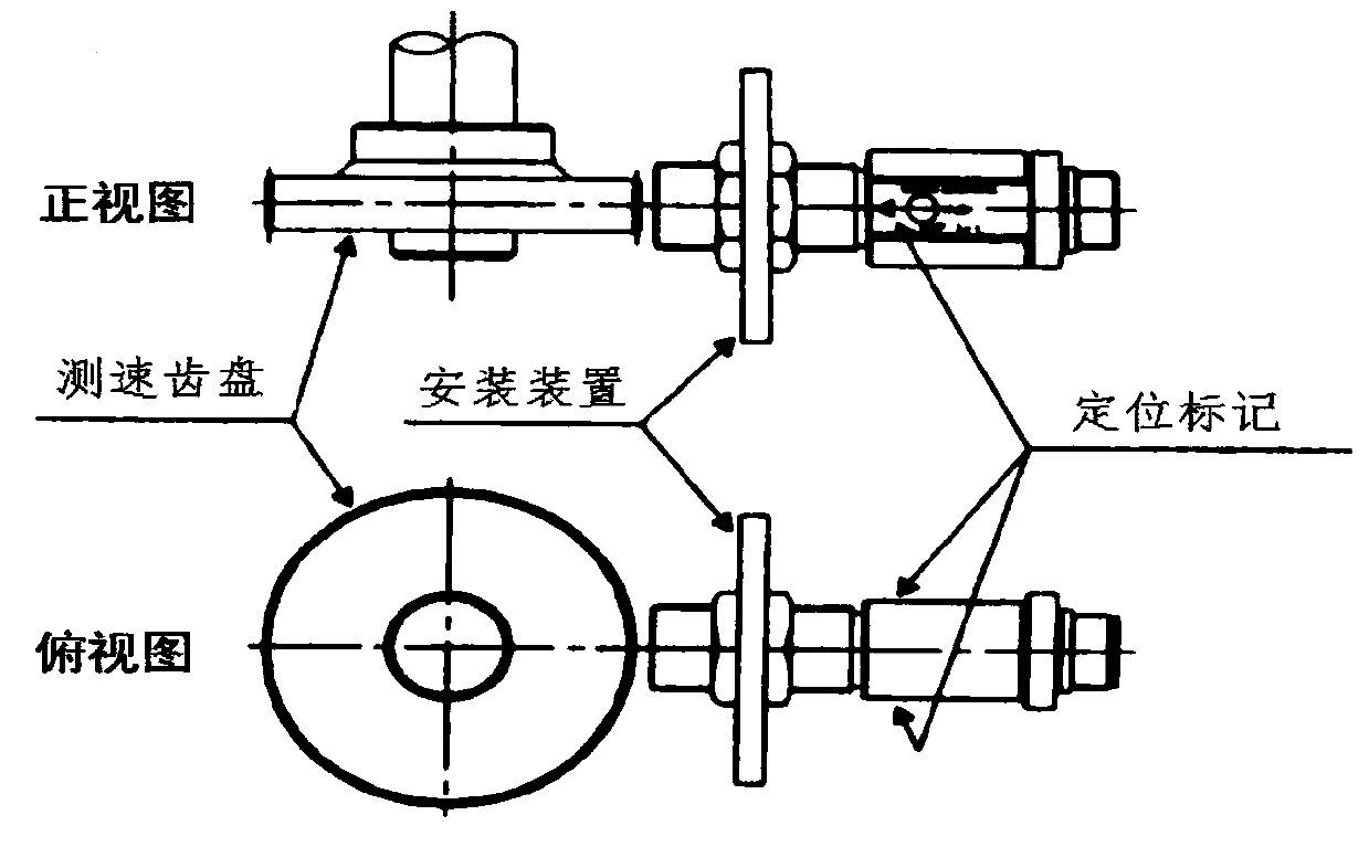

Image

  • A Method of Drilling 4 Holes in the Water Turbine Discharge Cone Based on Large Flow Deviated Working Conditions
  • A Method of Drilling 4 Holes in the Water Turbine Discharge Cone Based on Large Flow Deviated Working Conditions
  • A Method of Drilling 4 Holes in the Water Turbine Discharge Cone Based on Large Flow Deviated Working Conditions

Examples


Embodiment Construction

[0048]The technical solutions in the embodiments of the present invention will be clearly and completely described below in conjunction with the accompanying drawings in the embodiments of the present invention. Obviously, the described embodiments are only some of the embodiments of the present invention, not all of them. Based on the embodiments of the present invention, all other embodiments obtained by persons of ordinary skill in the art without making creative efforts belong to the protection scope of the present invention.

[0049] The invention provides a method for drilling 4 holes in the discharge cone of a water turbine based on a large flow and partial working condition.

[0050] Step 1. Use the unit speed n 11 and unit flow Q 11 To describe the flow conditions in the entire flow channel, the ambient pressure level in the test is changed by adjusting the cavitation coefficient σ of the device, and the unit speed and unit flow rate are changed by adjusting the open...


PUM

PropertyMeasurementUnit
Sensitivityaaaaaaaaaa

Abstract

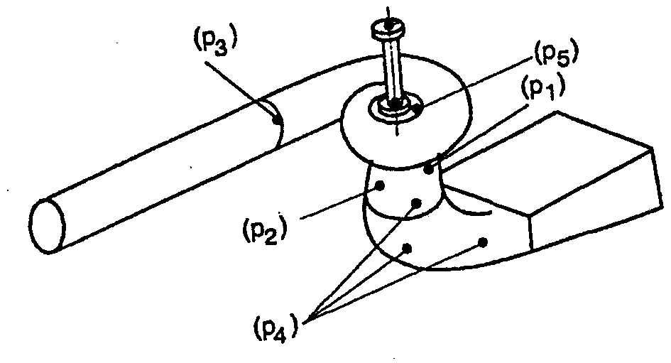
The invention provides a method for punching four holes for a runner cone of a water turbine on the basis of high-flow deviation working conditions. The method comprises steps as follows: pressure distribution of the runner cone and a draft tube part is determined according to the high-flow deviation working conditions, so that a low-pressure area range is determined, and a nascent place of a vortex zone is determined; the pressure distribution of the runner cone and the pressure distribution of the draft tube part are symmetric, a low-pressure area is located at an outlet of the runner cone, when pressure is lower than local vaporizing pressure, a cavitation vortex zone, namely, the nascent place of the vortex zone, is produced, a punching measure is implemented according to the nascent place of the vortex zone and comprises step of punching the four holes in the runner cone, and for the runner cone provided with the four holes, the runner cone provided with two holes is obtained through opposite punching along the axis of the short and straight runner cone, and then on the basis of the runner cone provided with the two holes, the other two holes are vertically and oppositely punched in the relatively lower position. With the adoption of the method, the problems of unsteady flow in a hydraulic turbine set, especially the problems of the vortex zone in the draft tube and corresponding pressure pulsation in the prior art are solved.

Description

technical field [0001] The invention belongs to the technical field of water turbine stability, and in particular relates to a method for drilling four holes in a water turbine discharge cone based on a large flow and off-working condition. Background technique [0002] Today, as the importance of hydropower generation becomes increasingly prominent, the requirements for improving the operating efficiency of hydropower stations and the stability of hydraulic turbines have become particularly prominent. Among the factors affecting the stable operation of the turbine, the hydraulic factor is the most prominent, including the dynamic and static interference between the rotating part and the stationary part, the shedding of the blade surface, the cavitation blade path vortex, and the cavitation draft tube vortex belt, etc. During the operation of the turbine, most of these flow phenomena occur in off-the-shelf conditions that deviate from the design conditions, which will induce...

Claims


Application Information

Patent Timeline
Patent Type & Authority Patents(China)
IPC IPC(8): B23B35/00F03B15/08F03B11/04G01M10/00
CPCB23B35/00F03B11/04F03B15/08G01M10/00Y02E10/20Y02P70/50
Inventor 苏文涛李小斌张甲
Owner 哈尔滨奈格科技发展有限公司
Learn More