
Layered heating device for laboratory reservoir

A laboratory and reservoir technology, applied to hydraulic models, etc.

Inactive Publication Date: 2017-06-13
TIANJIN UNIV
View PDF7 Cites 3 Cited by
  • Summary
  • Abstract
  • Description
  • Claims
  • Application Information

AI Technical Summary

Problems solved by technology

Therefore, the laboratory can naturally adjust the stratification temperature by water depth, which cannot be realized.

Method used


Image

  • Layered heating device for laboratory reservoir

Examples


Embodiment Construction

[0019] The present invention will be further described below in conjunction with the accompanying drawings.

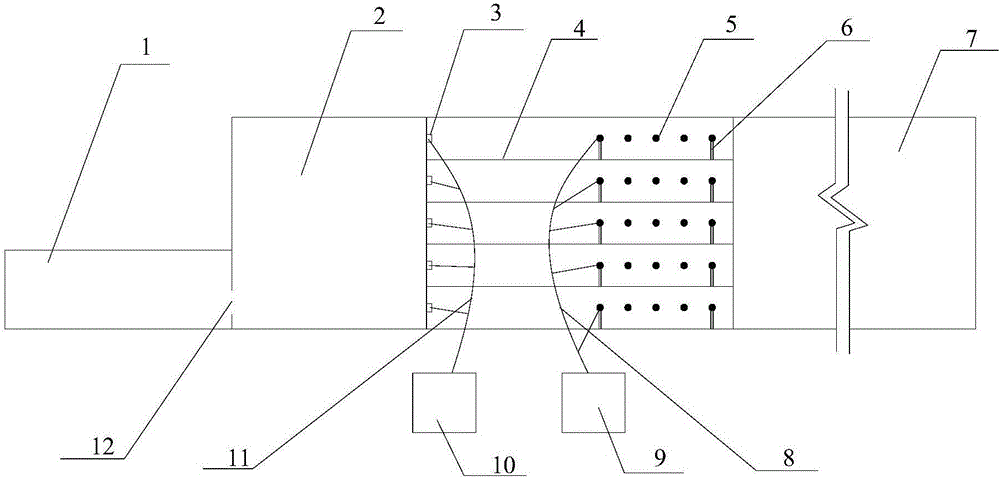
[0020] like figure 1 As shown, a laboratory reservoir layered heating device is composed of four parts: a lower pool 1, a test section, a layered heating section and an upper pool 7;

[0021] The lower pool 1 is a rectangular water tank made of reinforced concrete with a cross-sectional size of 1.2m×1m and a wall thickness of 15cm; the water discharged from the test flows away through the lower pool 1.

[0022] The test section is composed of a test tank 2 and a drain hole 12; the test tank 2 is a trapezoidal section tank, one end of which is blocked, and the size of the trapezoidal section is 1.5m at the bottom, 3m at the top, 2m high, and 20cm thick; the outside of the test tank 2 Supports can be provided to ensure structural safety; the blocked side of the test tank 2 is connected to the lower pool 1; a drain hole 12 is provided at the bottom of the blocked side, a...


PUM


Abstract

The invention discloses a layered heating device for a laboratory reservoir. The layered heating device comprises a lower pool, a test section, a layered heating section and an upper pool, wherein the lower pool is a rectangular water tank; the test section consists of a test water tank and a weep hole, the test water tank adopts a trapezoidal cross-section structure, the lower part of one end of the test water tank is communicated with the lower pool of the weep hole, and the other end is connected with the layer heating section; the layered heating section consists of temperature sensors, a layered box, resistance heating tubes, a support, electric wires, current controllers, temperature collectors and cables, the layered box has 4-12 layers, one end of the layered box is connected with the test water tank, and the other end is connected with the upper pool; the resistance heating tube on each layer is connected with the corresponding current controller through one electric wire, and each current controller can adjust current intensity of the resistance heating tube on each layer; the temperature sensor is arranged on the side wall of an outlet of each layer and connected with the corresponding temperature collector through one cable to test the water flow temperature of the outlet of each layer.

Description

technical field [0001] The invention relates to a layered heating device for a laboratory reservoir, in particular to a laboratory device which utilizes a layered heating method to realize the layered change of the water temperature of the reservoir along the depth. Background technique [0002] The water body temperature of deep-water large reservoirs generally has obvious temperature stratification along the depth direction, that is, the temperature of the surface layer is high, and the temperature of the bottom layer is relatively low. When carrying out the temperature change of the reservoir discharge flow in the laboratory, it is basically a scale model. According to the scale, the water depth of the laboratory model is very shallow, generally between tens of centimeters and one or two meters. Therefore, it is impossible for the laboratory to naturally adjust the stratification temperature by water depth. Therefore, the present invention proposes a laboratory reservoi...

Claims


Application Information

Patent Timeline
Patent Type & Authority Applications(China)
IPC IPC(8): E02B1/02
CPCE02B1/02
Inventor 王海军冯立阳练继建
Owner TIANJIN UNIV
Learn More