A method and device for obtaining calibration parameters

A technology of parameters and weight coefficients, applied in the field of obtaining correction parameters, which can solve the problems of difficult application of binocular cameras, no correction method given, and fields of view that cannot be completely overlapped.

Active Publication Date: 2020-05-19
广州民作信息科技有限公司
View PDF5 Cites 0 Cited by
  • Summary
  • Abstract
  • Description
  • Claims
  • Application Information

AI Technical Summary

Problems solved by technology

[0002] Depth information can be obtained by using a binocular camera, but due to a certain distance between the two cameras in the binocular camera, the field of view between the two cameras cannot completely overlap, so that when two cameras are used to shoot a point at the same time, The positions of this point on the images captured by the two cameras are not the same, which brings difficulties to the application of the binocular camera in the later stage. Therefore, it is necessary to correct the images captured by the two cameras in the binocular camera, while in the related art There is no effective correction method given

Method used


Image

  • A method and device for obtaining calibration parameters
  • A method and device for obtaining calibration parameters
  • A method and device for obtaining calibration parameters

Examples


Embodiment Construction

[0081] In order to facilitate the understanding of those skilled in the art, the present invention will be further described below in conjunction with the accompanying drawings, which cannot be used to limit the protection scope of the present invention. It should be noted that, in the case of no conflict, the embodiments in the present application and various manners in the embodiments can be combined with each other.

[0082] It should be understood that the specific embodiments described here are only used to explain the present invention, not to limit the present invention.

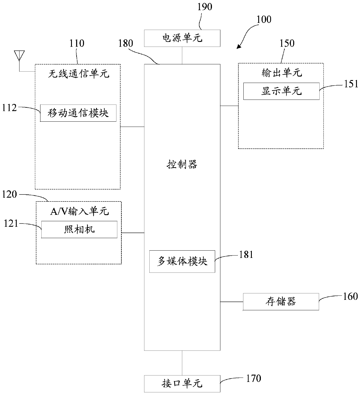
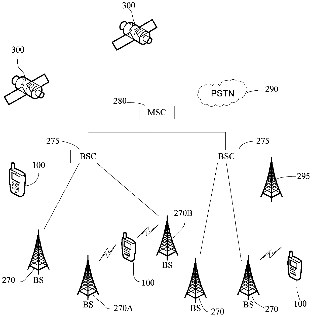
[0083] A mobile terminal implementing various embodiments of the present invention will now be described with reference to the accompanying drawings. In the following description, use of suffixes such as 'module', 'part' or 'unit' for denoting elements is only for facilitating description of the present invention and has no specific meaning by itself. Therefore, "module" and "component" may be used m...


PUM


Abstract

The invention relates to a method and a device for acquiring a correction parameter. The method comprises the steps of establishing coordinate systems: establishing a first physical coordinate system of a preset object, a second physical coordinate system and a corresponding first pixel coordinate system of a first camera, a third physical coordinate system and a corresponding second pixel coordinate system of a second camera, a fourth physical coordinate system and a corresponding third pixel coordinate system disposed between the second physical coordinate system and the third physical coordinate system; acquiring a first image of the preset object by use of the first camera, and meanwhile acquiring a second image of the preset object by use of the second camera; acquiring a third image which overlaps with the second image from the first image, and acquiring a fourth image which overlaps with the first image from the second image; and calculating a first parameter, used for correcting the image, of the first camera and a second parameter, used for correcting the image, of the second camera according to the established coordinate systems, the third image and the fourth image. The embodiment lays a foundation for subsequent image correction.

Description

technical field [0001] This article involves but is not limited to optical technology and terminal technology, especially a method and device for obtaining correction parameters. Background technique [0002] Depth information can be obtained by using a binocular camera, but due to a certain distance between the two cameras in the binocular camera, the field of view between the two cameras cannot completely overlap, so that when two cameras are used to shoot a point at the same time, The positions of this point on the images captured by the two cameras are not the same, which brings difficulties to the application of the binocular camera in the later stage. Therefore, it is necessary to correct the images captured by the two cameras in the binocular camera, while in the related art No effective correction method is given. Contents of the invention [0003] In order to solve the above problems, the embodiment of the present invention proposes a method for obtaining correct...

Claims


Application Information

Patent Timeline
Patent Type & Authority Patents(China)
IPC IPC(8): G06T7/80
Inventor 徐爱辉
Owner 广州民作信息科技有限公司
Why Eureka
Try Eureka