Heat dissipation air duct system special for construction

A heat dissipation air duct and building technology, applied in ventilation systems, household heating, household heating, etc., to achieve the effect of gentle indoor temperature changes

Inactive Publication Date: 2017-06-16
SUZHOU CROWNHOMES TIMBER STRUCTURE TECH CO LTD
View PDF11 Cites 2 Cited by
  • Summary
  • Abstract
  • Description
  • Claims
  • Application Information

AI Technical Summary

Problems solved by technology

[0003] Aiming at the above problems, the present invention provides a building-specific cooling air duct system, which utilizes an energy storage device and a reasonable air duct system to make the indoor temperature change gentle and stable, and is not easily affected by the outdoor temperature, and can be adapted to winter, summer and transition Seasonal requirements for temperature and ventilation have the advantage of economical and energy-saving

Method used


Image

  • Heat dissipation air duct system special for construction
  • Heat dissipation air duct system special for construction
  • Heat dissipation air duct system special for construction

Examples


Embodiment Construction

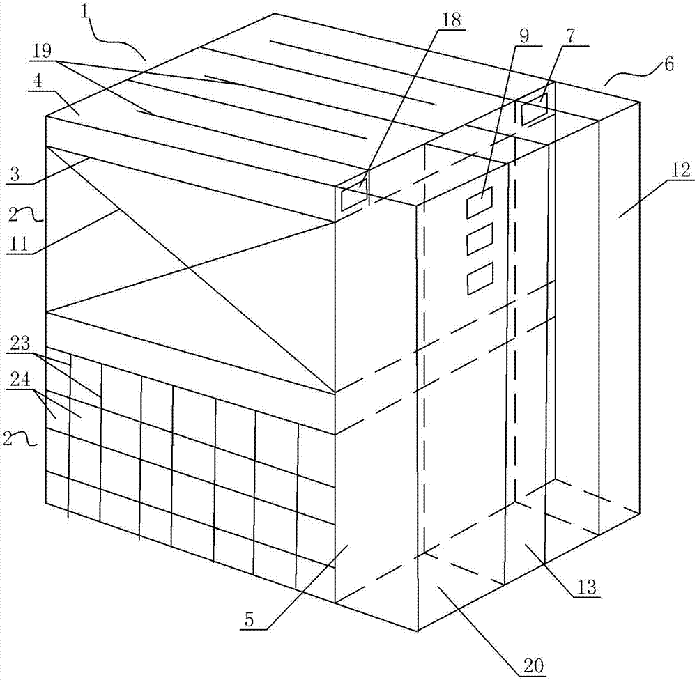
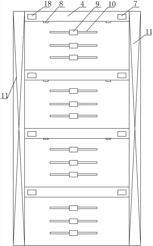
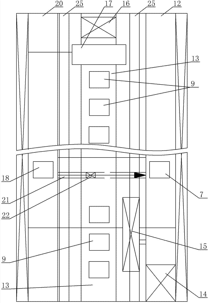
[0018] A special cooling air duct system for buildings, see Figure 1 ~ Figure 3 : It includes a main building 1, the main building 1 is provided with a plurality of floors 2, and it is characterized in that: the top of each floor 2 is separated by a top plate 3 to form an air intake cavity 4, and the ventilation facade 5 of the building main body 1 is less exposed to sunlight The outside is provided with a ventilated building area 6, and the ventilated building area 6 extends to the height of the entire ventilated façade 5, and the ventilated façade 5 is provided with an air inlet 7 corresponding to the position of the air inlet chamber 4 on each floor, and each air inlet chamber 4 The corresponding top plate 3 is provided with several air outlets 8 connected to all the rooms in the floor, and the ventilation facade 5 is provided with main air outlets 9 corresponding to the area of ​​each floor 2, and each main air outlet 9 passes through the external connection respectively. ...


PUM


Abstract

The invention provides a heat dissipation air duct system special for construction. An energy storage device and a reasonable air duct system are utilized, so that indoor temperature changes are gentle and stable, and indoor temperature is not subjected to the influence of outdoor temperature, and the heat dissipation air duct system can adapt to requirements for temperature and ventilation in winter, summer and transition seasons and have the advantages of being economical and saving energy. The heat dissipation air duct system comprises a main body building, and the main body building is provided with a plurality of floors. The heat dissipation air duct system is characterized in that the top of each floor is separated through a top plate to form an air inlet cavity, a ventilation building area is arranged on the outer side of a ventilation facade of the main body building with relatively less solar radiation, the ventilation building area is expanded to the height of the whole ventilation facade, the position of the ventilation facade corresponding to the air inlet cavity of each layer is provided with an air inlet, the top plate corresponding to each air inlet cavity is provided with a plurality of air feeding ports to be communicated with all rooms on the floor, and a main air outlet is arranged in the area of the ventilation facade corresponding to each floor.

Description

technical field [0001] The invention relates to the technical field of building ventilation, in particular to a building-specific cooling air duct system. Background technique [0002] With the increase of floors and effective volumes of high-rise buildings, the ventilation of the interior space of high-rise buildings has become an important factor that plagues the use of high-rise buildings. The air is turbid, which seriously endangers the physical and mental health of internal personnel. On the other hand, it also causes low heat dissipation efficiency inside the building, which leads to a serious temperature rise inside the building, which leads to a great increase in energy consumption for cooling inside, causing huge losses to users. Energy loss and economic burden, in order to overcome this problem, one of the commonly used methods is to set up multiple exhaust pipes to allow the building to exchange air by itself, but this method is inefficient in air exchange and can...

Claims


Application Information

Patent Timeline
IPC IPC(8): F24F7/08F24F13/30F24F13/02
CPCF24F7/08F24F13/0227F24F13/30
Inventor 陈勇沈周
Owner SUZHOU CROWNHOMES TIMBER STRUCTURE TECH CO LTD
Why Eureka
Try Eureka