
Vacuum cleaner

A technology for vacuum cleaners and separators, which is applied in the direction of vacuum cleaners, suction filters, suction hoses, etc., and can solve the problems of reducing the separation efficiency of separators and increasing reentry

Active Publication Date: 2017-06-20
DYSON TECH LTD
View PDF15 Cites 11 Cited by
  • Summary
  • Abstract
  • Description
  • Claims
  • Application Information

AI Technical Summary

Problems solved by technology

As such, the axis of the separator is rotated away from the vertical, which can reduce the separation efficiency of the separator and lead to increased re-entanglement of dirt from the dirt collector

Method used


Image

  • Vacuum cleaner
  • Vacuum cleaner
  • Vacuum cleaner

Examples


Embodiment Construction

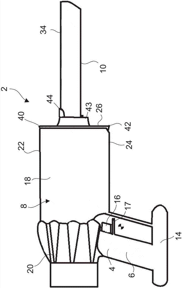
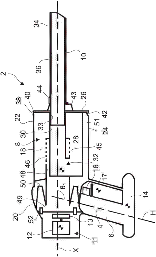
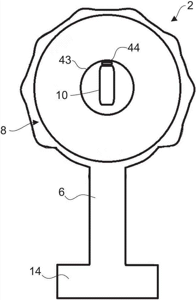
[0022] figure 1 with 2 A hand-held vacuum cleaner 2 is shown comprising a main body 4 having an elongated handle 6; a cyclonic unit 8 having a longitudinal axis X; and a cleaning implement 10 in the form of a nozzle secured to the cyclonic unit 8. . The cyclonic separation unit 8 extends away from the handle 6 such that the cleaning implement 10 is at the end of the cyclonic separation unit 8 furthest from the handle 6 . The cleaning tool 10 extends away from the cyclonic separation unit 8 along the longitudinal axis X of the cyclonic separation unit 8 .

[0023] The main body 4 also includes a suction generator 11 comprising a motor 12 and an impeller 13 positioned above the handle 6 and near the rear of the handle; and an accumulator 14 positioned directly below the handle. An actuator 16 in the form of a finger operated trigger is provided at the upper part of the handle. A trigger guard 17 extends forwardly from the handle below the trigger 16 . The handle 16 is arran...


PUM


Abstract

A handheld vacuum cleaner (2) comprising a handle (6) by which the vacuum cleaner is supported during use, a cyclonic separating unit (8) comprising a separator (18) having a cyclone chamber (28) which defines a separator axis X and an inlet duct (30, 36) having an inlet duct axis which is substantially parallel with the separator axis X. The cyclonic separating unit (8) extends at least partly around a portion of the inlet duct (30, 36).

Description

technical field [0001] The present invention relates to a hand-held vacuum cleaner comprising a cyclonic separation unit, and to a stick vacuum cleaner comprising a hand-held vacuum cleaner. Background technique [0002] EP2040597A discloses a handheld vacuum cleaner comprising a cyclone unit extending along the handle. A difficulty with such vacuum cleaners is that the cyclonic separation unit blocks access to narrow gaps, such as those formed between items of furniture or between an appliance and a wall. In order to clean these gaps, cleaning implements such as sticks or specially designed cleaning nozzles have to be used. [0003] GB2484146A discloses a stick vacuum cleaner, including a hand-held vacuum cleaner, similar to the vacuum cleaner disclosed in EP2040597A. Stick vacuum cleaners are formed by attaching a stick to the vacuum cleaner, and attaching cleaning heads to opposite ends of the stick. Such stick vacuum cleaners are increasingly being used as an alternat...

Claims


Application Information

Patent Timeline
Patent Type & Authority Applications(China)
IPC IPC(8): A47L5/24A47L9/16
CPCA47L5/24A47L9/16A47L5/28A47L9/165A47L9/1625A47L9/1641A47L9/1666A47L9/242A47L9/1683A47L9/1616A47L9/24
Inventor S·R·迪姆拜洛
Owner DYSON TECH LTD
Features
  • Generate Ideas
  • Intellectual Property
  • Life Sciences
  • Materials
  • Tech Scout
  • Unparalleled Data Quality
  • Higher Quality Content
  • 60% Fewer Hallucinations
Learn More