Cyclone separating apparatus and a vacuum cleaner having the same

a technology of cyclone separation and vacuum cleaner, which is applied in the direction of auxillary pretreatment, cleaning filter means, separation processes, etc., can solve the problems of deteriorating suction force and cleaning efficiency, cleaners are difficult to keep, and the conventional cyclone separation apparatus has problems, so as to improve dust collection efficiency and prevent deterioration of suction force

Inactive Publication Date: 2007-01-30
SAMSUNG GWANGJU ELECTRONICS CO LTD
View PDF18 Cites 57 Cited by
  • Summary
  • Abstract
  • Description
  • Claims
  • Application Information

AI Technical Summary

Benefits of technology

[0008]An object of the present invention is to solve at least the above problems and / or disadvantages and to provide at least the advantages described below. Accordingly, an object of the present invention is to provide a cyclone separating apparatus with a compact structure that is capable of improving dust-collecting efficiency in a plurality of the conventional cyclone dust-collecting apparatuses, and prevents deterioration of suction force, and a vacuum cleaner having the same.
[0011]The grill member may comprise a grill body with a plurality of channels. A grill opening is formed on one side of the grill body for discharging air from which dust or dirt has been separated by communicating with the first outlet. A shielding member is formed on the other side of the grill body for preventing dust from flowing backward.

Problems solved by technology

The conventional cyclone separating apparatus, however, has some problems.
First, since the connecting structure between the first cyclone and the auxiliary cyclone is complicated, and a suction force generated from a main body of the vacuum cleaner is difficult to be properly delivered, the suction force and cleaning efficiency is deteriorated.
Secondly, since the first cyclone and the auxiliary cyclone are not compactly arranged, the cyclone separating apparatus indispensably requires a big volume to properly perform an appropriate dust-collecting function.
Accordingly, the vacuum cleaner with the above cyclone separating apparatus is large in its structure, the cleaner is difficult to keep, and the cleaning task is inconvenient to a user.
Thirdly, since a connection path between the first cyclone and the auxiliary cyclone is complicated, a production process is complicated.
Therefore, the number of parts and production costs are increased.

Method used


Image

  • Cyclone separating apparatus and a vacuum cleaner having the same
  • Cyclone separating apparatus and a vacuum cleaner having the same
  • Cyclone separating apparatus and a vacuum cleaner having the same

Examples


Embodiment Construction

[0024]Certain embodiments of the present invention will now be described with reference to the accompanying drawings.

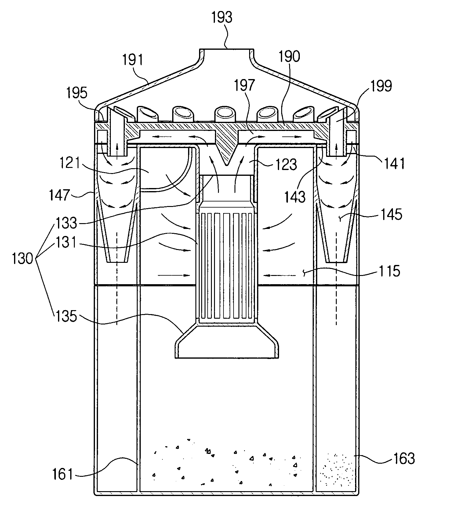
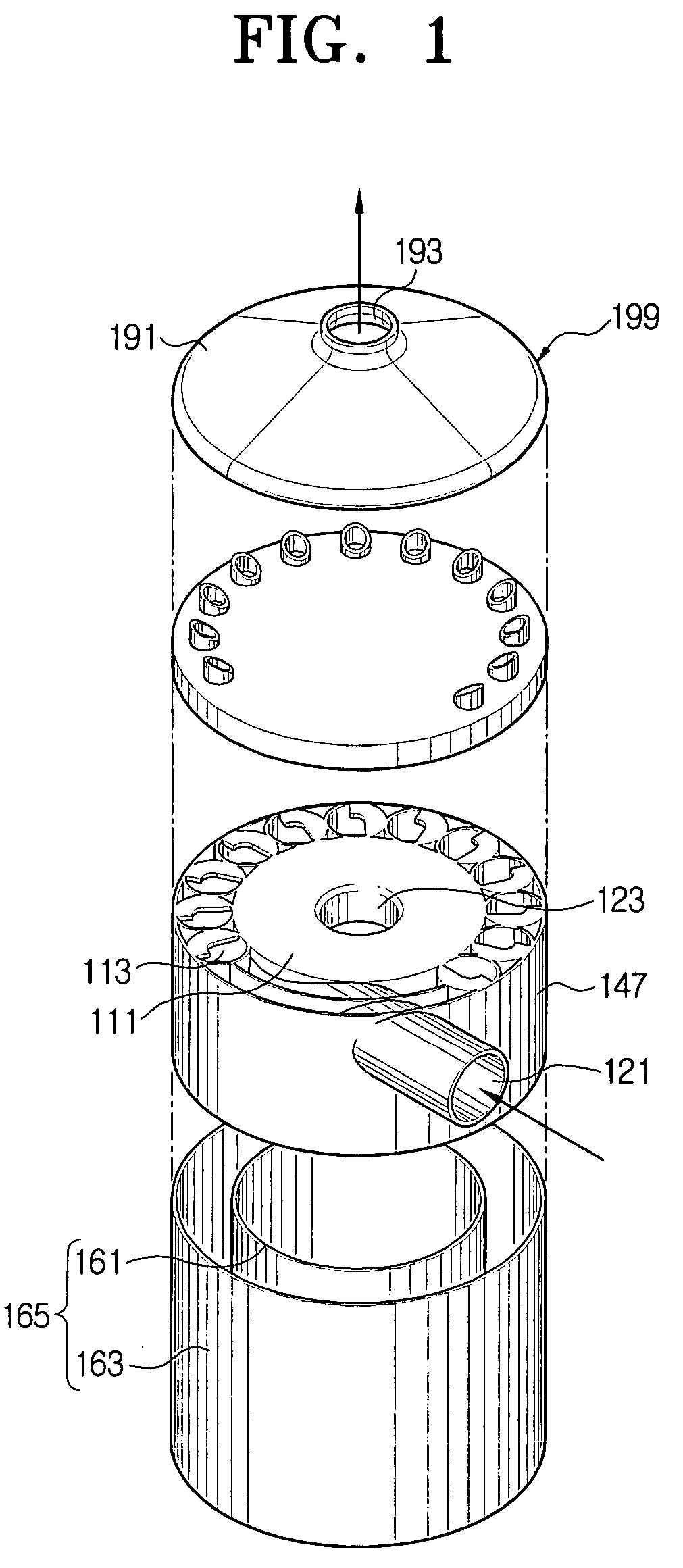
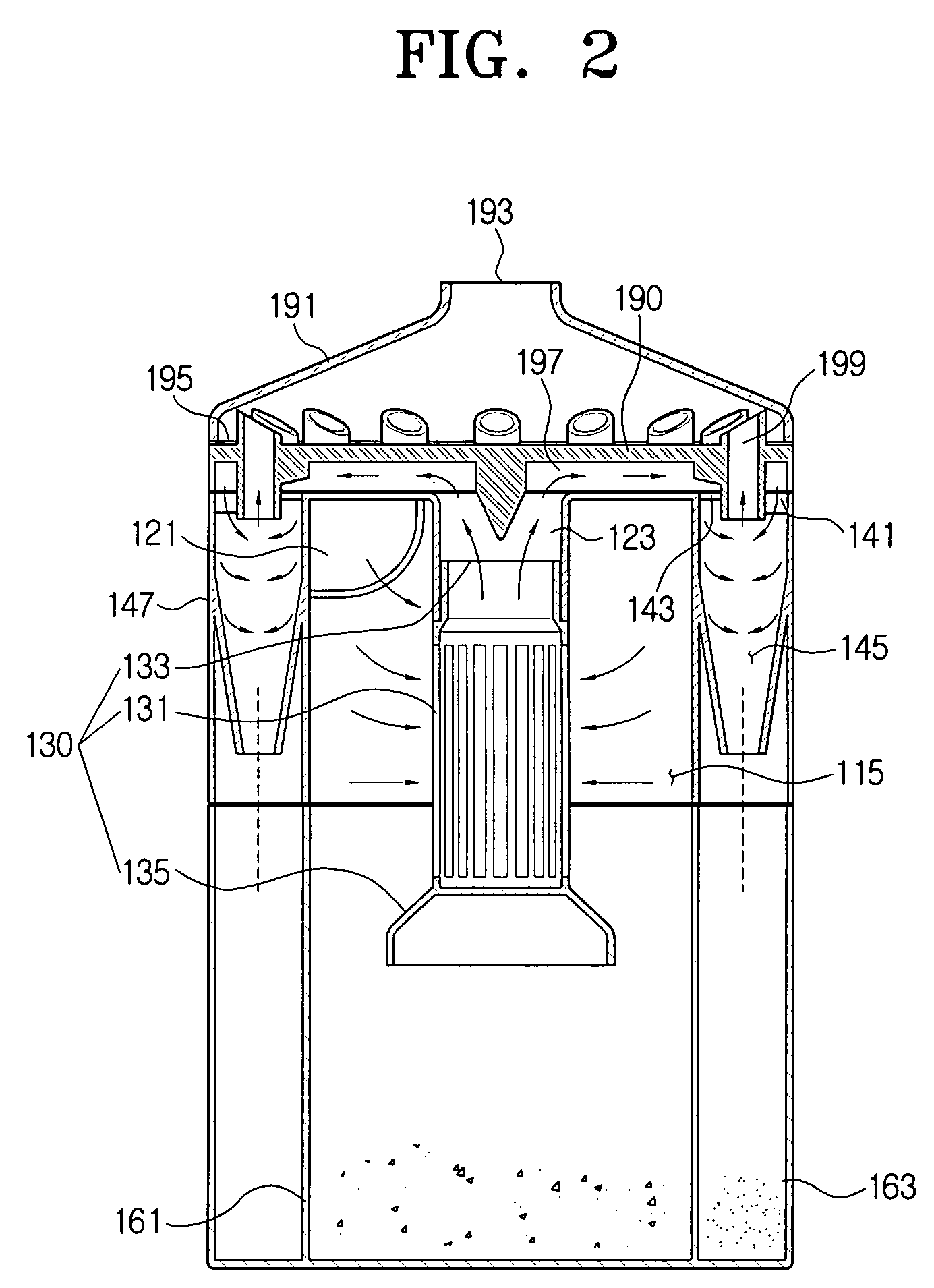
[0025]The cyclone separating apparatus according to the present invention includes, a first cyclone 111, a plurality of second cyclones 113, an inlet-outlet cover 190 installed on the upper part of the first cyclone 111 and the second cyclones 113, a cyclone cover 191, and a dust collecting unit 165. A plurality of the second cyclones 113 are installed on the outer periphery of the first cyclone 111 to enclose the first cyclone 111. The first cyclone 111 and each of the second cyclones 113 are integrally formed, and a partition 250 is installed between the second cyclones 113, as shown in FIG. 3. The partition 250 partitions space between the second cyclones 113 to form the cyclone separating apparatus 100. A chamber wall 147 is formed in a cylindrical shape around the second cyclones 113. The chamber wall 147 can be formed with a variety of polygonal shapes depending...


PUM

PropertyMeasurementUnit
centrifugal forceaaaaaaaaaa
conical shapeaaaaaaaaaa
discharging currentaaaaaaaaaa

Abstract

A cyclone separating apparatus and a vacuum cleaner having the same are disclosed. More specifically, the cyclone separating apparatus for a vacuum cleaner comprises a first cyclone for separating drawn-in air, and a plurality of second cyclones installed on an outer periphery of the first cyclone to enclose the first cyclone. Accordingly, because a plurality of the cyclones separates dust, and a bulky structure is improved to a compact structure, suction force deterioration does not occur, and, dust-collecting efficiency is increased.

Description

REFERENCE TO RELATED APPLICATION[0001]This application claims priority to Korean Application No. 2003-62520, filed Sep. 8, 2003, in the Korean Intellectual Property Office, the disclosure of which is incorporated herein by reference.CROSS-REFERENCE TO RELATED APPLICATIONS[0002]This application is related to applications entitled “Cyclone Separating Apparatus and Vacuum Cleaner having the same” (U.S. application Ser. No. 10 / 840,230, filed May 7, 2004), “Cyclone Dust Separating Apparatus and Vacuum Cleaner having the same” (U.S. application Ser. No. 10 / 840,231, filed May 7, 2004), and “Cyclone Separating Apparatus and Vacuum Cleaner Equipped with the same” (U.S. application Ser. No. 10 / 840,229, filed May 7, 2004, now U.S. Pat. No. 7,097,680, issued Aug. 29, 2006), whose disclosures are commonly owned by the same assignee as the present application and are entirely incorporated herein by reference.FIELD OF THE INVENTION[0003]The present invention is generally related to a cyclone separ...

Claims


Application Information

Patent Timeline
Patent Type & Authority Patents(United States)
IPC IPC(8): B01D45/12A47L9/16B04C5/13B04C5/24B04C5/26
CPCA47L9/1625A47L9/1641B04C5/24B04C5/26B04C5/13Y10S55/03A47L9/16
Inventor OH, JANG-KEUNHAN, JUNG-GYUN
Owner SAMSUNG GWANGJU ELECTRONICS CO LTD
Why Eureka
Try Eureka