Multistage cyclone separation device of dust collector

A technology of cyclone separation device and vacuum cleaner, which is applied in the direction of suction filter, etc., can solve the problems of restricting the separation efficiency of the secondary separation device and reducing the dust removal efficiency

Inactive Publication Date: 2010-10-20
马吉
View PDF1 Cites 34 Cited by
  • Summary
  • Abstract
  • Description
  • Claims
  • Application Information

AI Technical Summary

Problems solved by technology

These factors restrict the separation efficiency of the secondary separation device, thereby reducing the overall dust removal efficiency

Method used


Image

  • Multistage cyclone separation device of dust collector
  • Multistage cyclone separation device of dust collector
  • Multistage cyclone separation device of dust collector

Examples


Embodiment Construction

[0025] Below in conjunction with accompanying drawing, specifically illustrate the utility model:

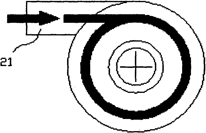
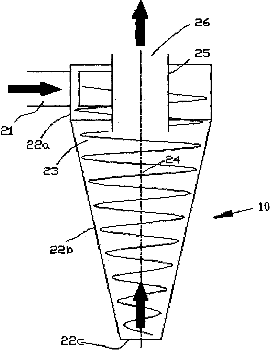
[0026] Such as figure 1 and figure 2 What is shown is a structural schematic diagram of a cyclone cylinder in a multi-stage cyclone separation device for a vacuum cleaner in the prior art. The cylinder (22a) of the cyclone body (20) is provided with a tangential air inlet (21) and an exhaust port (505), and the inner cavity (23) of the cyclone body (20) forms a cyclone separation chamber. The separated small particle ash enters the dust collection chamber (not shown in the figure) through the terminal ash discharge port (22c), and the clean air is discharged from the exhaust port (505) through the exhaust pipe (504).

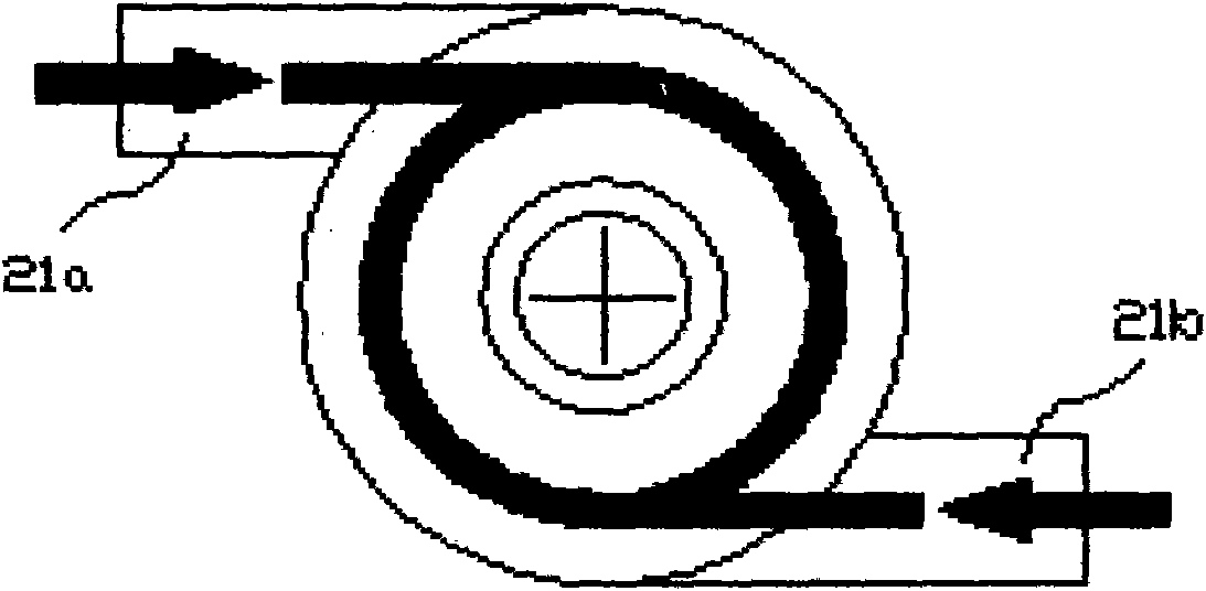
[0027] image 3 and Figure 4 Shown is a schematic diagram of the structure of the cyclone cylinder in the multi-stage cyclone separation device for the vacuum cleaner used in the present invention. The cyclone cylinder (20) is frusto-conical and consists of...


PUM


Abstract

The invention relates to a multistage cyclone separation device of a dust collector, which comprises an upstream first-stage cyclone separation device (1), a downstream second-stage cyclone separation device (2) and a gas flow channel (3), wherein the gas flow channel (3) is used for connecting the upstream first-stage cyclone separation device (1) and the downstream second-stage cyclone separation device (2), the downstream second-stage cyclone separation device (2) comprises a cyclone filter (5), a dust-gas separation cover (6) and a central cylinder (8), at least two tangential air inlets are arranged on the cylindrical later surface of a cyclone cylinder body (20), an exhaust pipe (504) is positioned on the cylindrical top surface of the cyclone cylinder body (20), and the tangential air inlets have equal cross sectional area, are positioned on the same horizontal surface and are arranged relatively to the central shaft of the cyclone cylinder body (20) according to equal phase difference. The invention has the advantages that the short-circuit flow of the exhaust pipe is less than that of a single-gas inlet cyclone separation device, the axial symmetry of a flow field is more excellent, and the proportion that small-granule dust directly enters an exhaust port without cyclone separation after entering a separation chamber is reduced.

Description

technical field [0001] The invention relates to a multi-stage cyclone separation device for a vacuum cleaner. Background technique [0002] The multi-stage cyclone separation device of the vacuum cleaner uses the cyclone principle to filter the air containing dust or solid particles through the upstream primary cyclone separation device to initially filter out large particles of dust, and then further filter and remove small particles of dust through the downstream secondary cyclone separation device, thereby To achieve the purpose of purifying the air. In the prior art, as U.S. Patent No. 4,373,228 discloses a vacuum cleaner using a secondary cyclone separation device, the structure of the separation device includes at least an upstream primary cyclone separation device and a downstream secondary cyclone separation device The primary cyclone separation device includes an outer barrel with a primary integration chamber, and the secondary cyclone separation device includes a...

Claims


Application Information

Patent Timeline
Patent Type & Authority Applications(China)
IPC IPC(8): A47L9/16
Inventor 马吉哈瑞
Owner 马吉
Why Eureka
Try Eureka