Drilling tool with dust collector

a technology of dust collector and drilling tool, which is applied in the field of drilling tools, can solve the problems of increased cost, lack of portability of devices, and lack of portability of methods, and achieve the effects of improving workability, reducing size, and increasing dust collection efficiency

Inactive Publication Date: 2009-06-11
HITACHI KOKI CO LTD
View PDF20 Cites 34 Cited by
  • Summary
  • Abstract
  • Description
  • Claims
  • Application Information

AI Technical Summary

Benefits of technology

[0011]An object of the present invention is to provide a drilling tool having a dust collector which is increased in dust collection efficiency, improved in workability, and reduced in size.

Problems solved by technology

However, large-sized bellows member and dust collection box are required, and the suction dust collector as the separate device is also required so that the method lacks portability.
Even in this device, the compressor as an external device is required so that the device lacks portability.
In addition, since the device has a special structure in which the fluid through passage is formed in the shaft center portion of the drill bit, the cost is increased.
However, there has been a case where the dust is not sufficiently sucked and the dust is leaked from the vicinity of a contacting area of the dust collection adaptor and the drill bit so that an operator has to spend extra time and effort.
However, there has been a case where a part of the dust remains inside the drilled hole after the drilling operation, the remaining dust needs to be removed when an anchor or the like is driven into the drilled hole, and the dust is disadvantageously blown off during the operation for removing the dust.
In particular, in the drilling operation with the drill bit faced downwardly as well as the drilling operation with the drill bit held laterally, there has been a case where the dust tends to remain inside the drilled hole or in the surrounding area thereof due to the influence of gravity, and the removal operation of the remaining dust requires extra time and effort.

Method used


Image

  • Drilling tool with dust collector
  • Drilling tool with dust collector
  • Drilling tool with dust collector

Examples


first embodiment

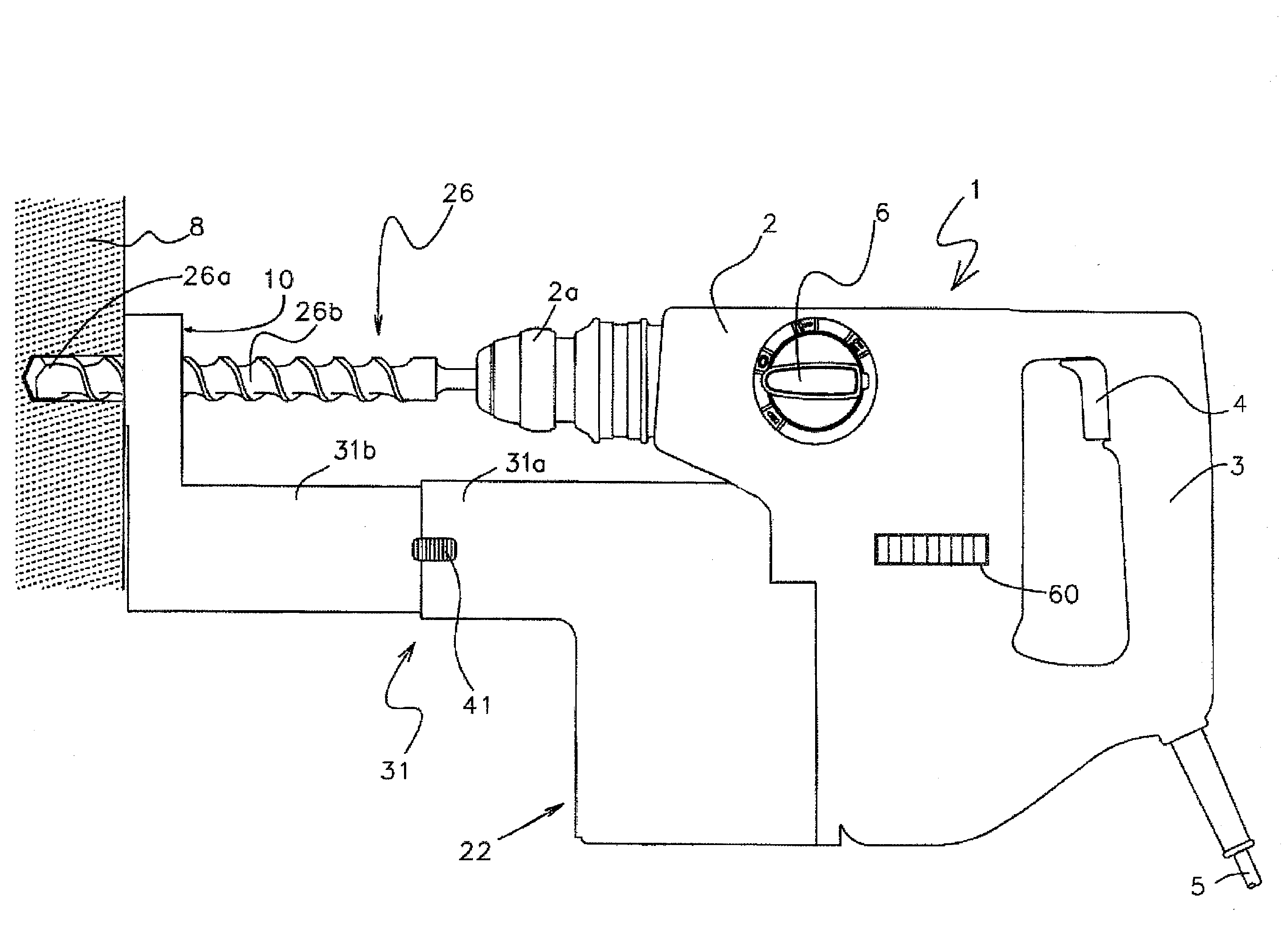
[0056]Although the present invention has been described thus far, various applications and modifications may be made in the embodiment. FIG. 3 shows an example of the modification. The operator withdraws the drill bit 26 from a drilled hole 8a after the production of the drilled hole 8a. Next, the blowoff port 10a of the dust collection adaptor 10 is moved close to the drilled hole 8a such that its center axis is positioned in the drilled hole 8a. Then, when the motor 18 is driven by operating the switch 4, the air blown from the blowoff port 10a flows into the drilled hole 8a which is opened in the axial direction of the drill bit 26, blows the remaining dust out of the drilled hole 8a, and guides the remaining from the dust collection port 10b to the dust collection passage 11. With this operation, it becomes possible to favorably remove the dust remaining in the drilled hole.

[0057]As for the amount of the air moved to the dust collection case 12 and the amount of the air blown fr...

second embodiment

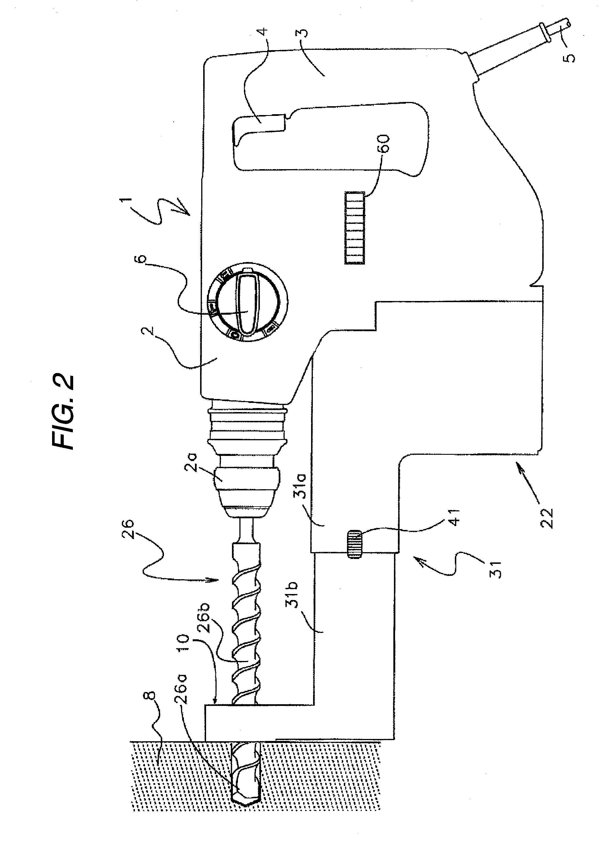
[0059]Next, a drilling tool showing the present invention will be described by using FIGS. 5 to 12. FIG. 5 shows an overall view of a drilling tool having a dust collector. Portions which are the same as those shown in FIG. 1 are designated by the same reference numerals, and their repeated descriptions will be omitted.

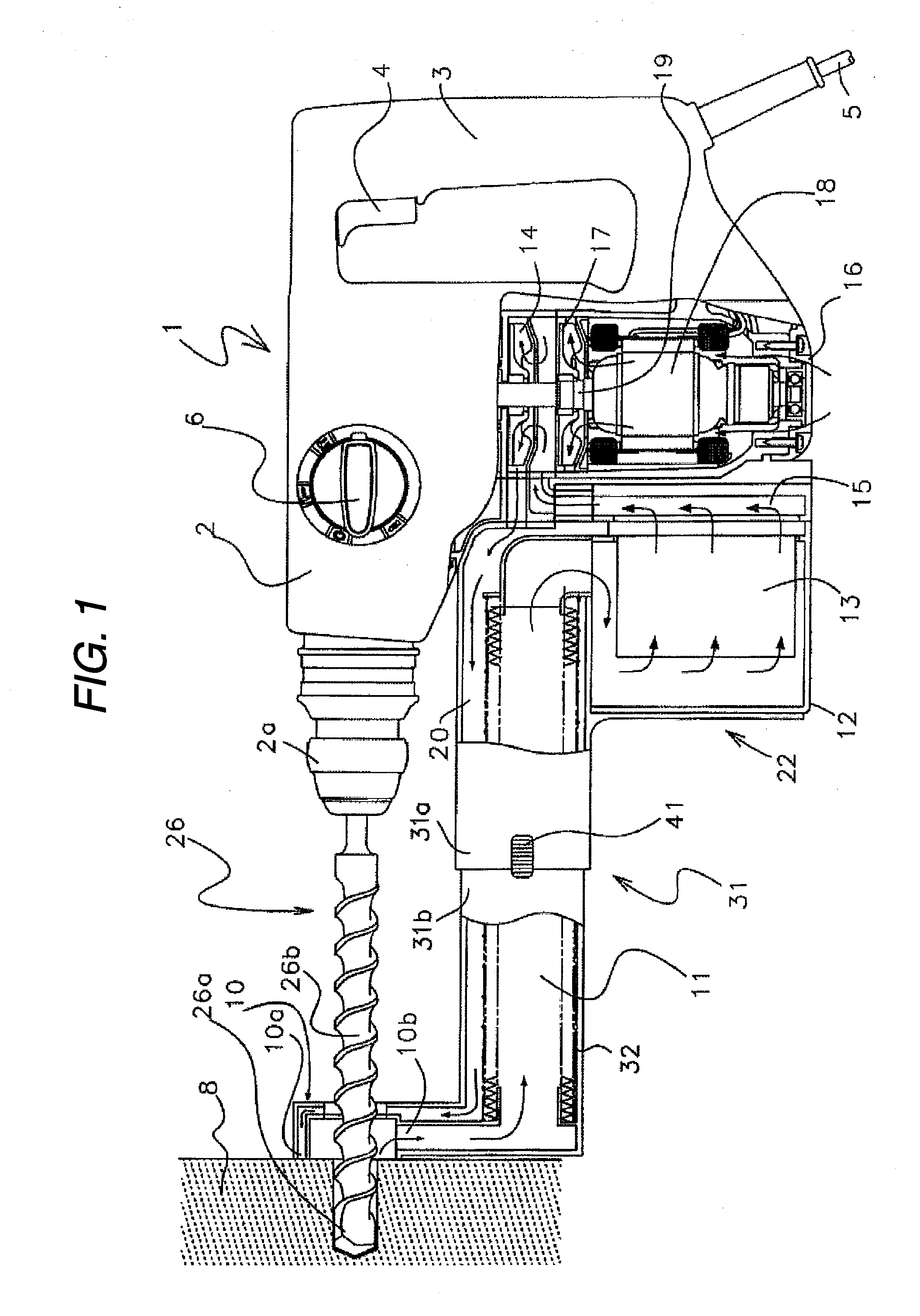
[0060]The housing 2 accommodates a motor portion, a cylinder portion, a handle portion, and a transmission drive unit. In the housing 2, the motor 18 as a driving source is vertically accommodated. At an upper end of an output shaft (motor shaft) 19 extending upwardly above the motor 18, a pinion 38 is integrally formed. On both sides of the output shaft 19 of the motor 18, a crankshaft 39 and an intermediate shaft 40 are vertically and rotatably supported, and gears are attached to the intermediate height positions of the crankshaft 39 and the intermediate shaft 40. These gears are engaged with the pinion 38 described above which is formed at the end portion of the m...

fourth embodiment

[0093]In the fourth embodiment, as a device to increase the inflow pressure, a guide portion 138 protruding toward the direction of the center of the centrifugal fan is additionally formed adjacent to the downstream side of the airflow sending port 136. The detail thereof will be described by using FIG. 20. FIG. 20 is a partially enlarged view for illustrating a positional relation of the guide portion 138 of FIG. 6.

[0094]In FIG. 20, in order to indicate the position of the cylindrical inner wall of the housing, a reference line 139 in the dashed line is drawn. As can be seen from the comparison between the reference line 139 and the state of the protrusion of the guide portion 138, the guide portion 138 obtained by protruding the inner wall portion on the downstream side of the airflow sending port 136 by the distance B in the direction of the center of the centrifugal fan is formed. Thus, by forming the guide portion 138, the airflow flowing toward the direction indicated by an ar...


PUM

PropertyMeasurementUnit
rotation forceaaaaaaaaaa
sizeaaaaaaaaaa
suction forceaaaaaaaaaa

Abstract

According to the invention, a drilling tool includes: a motor; a transmission drive unit for transmitting a rotation force of the motor to rotate a drill bit; and a dust collector for collecting dust produced from a workpiece drilled by the drill bit, wherein the dust collector is provided with a pierced portion pierced by the drill bit, a dust collection port for sucking the produced dust and its surrounding air, and a blowoff port for blowing air against a vicinity of the piercing drill bit.

Description

CROSS-REFERENCE TO RELATED APPLICATIONS[0001]This application is based upon and claims the benefit of priority from Japanese Patent Application No. 2007-316696 filed Dec. 7, 2007, and Japanese Patent Application No. 2008-087292 filed Mar. 28, 2008, the entire contents of which are incorporated herein by reference.BACKGROUND[0002]1. Field[0003]The present invention relates to a drilling tool for drilling a hole which is driven by an electric motor, an engine, or the like and, particularly, relates to a drilling tool with a dust collector which allows effective collection of dust produced during drilling.[0004]2. Description of the Related Art[0005]A drilling tool is used to drill a hole in stone materials such as a concrete and a brick. The drilling tool drills a hole in a workpiece by driving a drill bit, and includes a general rotary drill, a hammer drill which causes the drill bit to rotate and strike, a vibratory drill, or the like. Since dust is produced when a drilling operatio...

Claims


Application Information

Patent Timeline
Patent Type & Authority Applications(United States)
IPC IPC(8): B23B47/00
CPCY10T408/50B23Q11/006Y10T408/453
Inventor NISHIKAWA, TOMOMASAKOBORI, KENJISUZUURA, TSUKASA
Owner HITACHI KOKI CO LTD
Why Eureka
Try Eureka