Structure for motor, fan and cyclonic separation apparatus

A separation device and cyclone separator technology, applied in the installation of motor fan components, exhaust diffuser, electrical equipment, etc., can solve the problems of low separation efficiency, reduce energy loss, suppress high frequency Sound, total noise reduction effect

Inactive Publication Date: 2013-04-17
BLACK & DECKER INC
View PDF14 Cites 60 Cited by
  • Summary
  • Abstract
  • Description
  • Claims
  • Application Information

AI Technical Summary

Problems solved by technology

The separation efficiency of the first cyclonic separation unit is lower than the separation efficiency of the second cyclonic separation unit

Method used


Image

  • Structure for motor, fan and cyclonic separation apparatus
  • Structure for motor, fan and cyclonic separation apparatus
  • Structure for motor, fan and cyclonic separation apparatus

Examples


Embodiment Construction

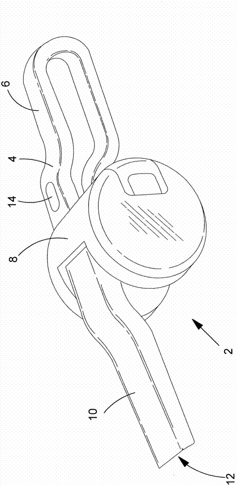
[0079] refer to figure 1 , which shows a first embodiment of a hand-held vacuum cleaner 2 comprising: a main body 4; a handle 6 connected to the main body 4; a cyclonic separation device 8 mounted on the main body and transversely across the main body; and a dirty air channel 10 having a dirty air inlet 12 at one end. The vacuum cleaner includes: an electric motor that engages a fan for generating air flow through the vacuum cleaner; and a rechargeable battery (not shown) Provides electrical energy to the motor when electrically connected to the motor.

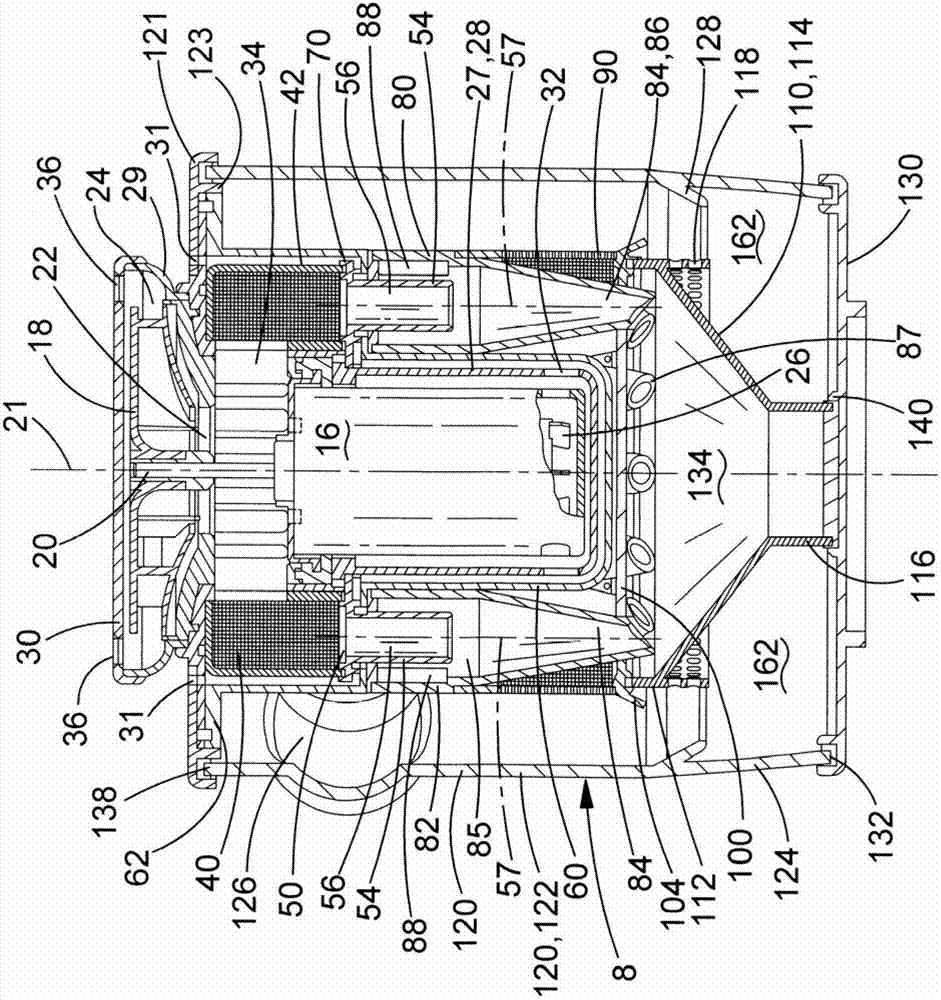
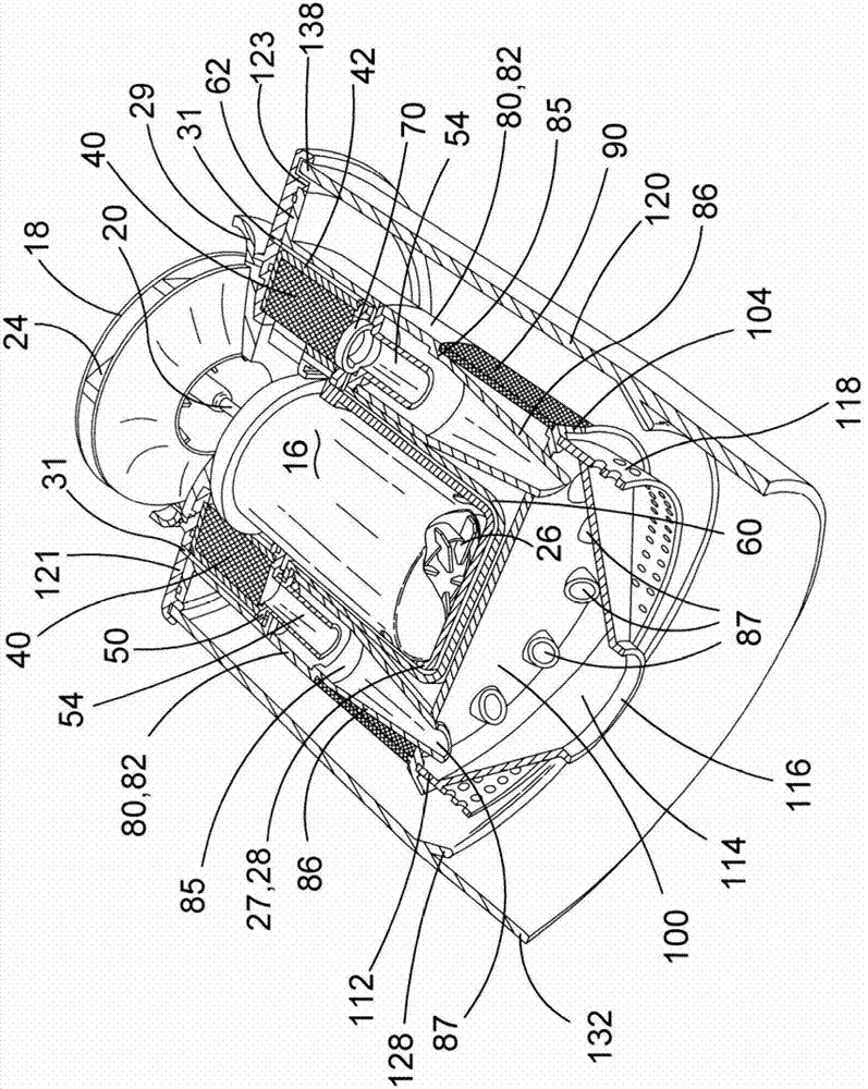
[0080] refer to Figure 2 to Figure 8 , which shows a structure including a motor 16, a fan 18 and a cyclonic separation device 8. The electric motor has a drive shaft 20 with a central axis 21 . The fan is a centrifugal fan 18 with an axial inlet 22 facing the motor and a tangential outlet 24 . The diameter of the fan is 68mm. The fan is mounted on the drive shaft that sits on top of the motor. In use, an electric moto...


PUM


Abstract

A motor, fan and cyclonic separation apparatus arrangement for a vacuum cleaner, the arrangement comprising: a motor (16) coupled to a fan (18) for generating air flow,a cyclonic separation apparatus (8) located in a path of the air flow generated by the fan,and a pre-fan filter (40) located in the path of the air flow downstream of the cyclonic separation apparatus and upstream of the fan (18), wherein the cyclonic separation apparatus comprises at least one cyclone (84) comprising: a cyclone body (85,86) with a longitudinal axis (57),an air inlet port (88) arranged tangentially through a side of the cyclone body,and an air outlet port (56) through a longitudinal end of the cyclone body, wherein the pre-fan filter (40) is arranged upon the air outlet port of the or each cyclone.

Description

technical field [0001] The present invention relates to the structure of electric motor, fan and cyclone type separating device. The invention relates particularly, but not exclusively, to the construction of electric motors, fans and cyclonic separation devices for use in vacuum cleaners. Background technique [0002] Vacuum cleaners are well known for collecting dust and dirt, but wet and dry variant vacuum cleaners capable of collecting liquids are also known. Typically vacuum cleaners are intended for use in residential environments, but they may also be used in other environments such as construction sites or gardens. Typically, they are powered by electricity and thus include: an electric motor; a fan connected to the output shaft of the motor; an inlet for dirty air; an outlet for clean air; and for dust, dirt (and possibly liquids) collection chamber. Power for the motor may be provided by mains power, in which case the vacuum cleaner will also include a power cor...

Claims


Application Information

Patent Timeline
Patent Type & Authority Applications(China)
IPC IPC(8): A47L9/16A47L9/28A47L9/00A47L9/12
CPCA47L9/0081A47L9/1641A47L9/1666A47L9/22
Inventor 凯文·史密斯
Owner BLACK & DECKER INC
Why Eureka
Try Eureka