Cyclonic separating apparatus

a technology of separating apparatus and cyclonic force, which is applied in the direction of cleaning equipment, domestic applications, applications, etc., to achieve the effect of improving the consistency of fluid flow ra

Inactive Publication Date: 2014-12-18
DYSON TECH LTD
View PDF1 Cites 60 Cited by
  • Summary
  • Abstract
  • Description
  • Claims
  • Application Information

AI Technical Summary

Benefits of technology

[0019]From another aspect, the invention provides a separating apparatus of the cyclonic type including a first cyclonic separating unit and a second cyclonic separating unit downstream from the first cyclonic separating unit. The second cyclonic separating unit includes a plurality of cyclones arranged fluidly in parallel. Each of the plurality of cyclones in the second cyclonic separating unit includes a first end having a fluid inlet and a fluid outlet, and a second end ha...

Problems solved by technology

This is a significant challenge, particularly in cyclone arrangement in which fir...

Method used


Image

  • Cyclonic separating apparatus
  • Cyclonic separating apparatus
  • Cyclonic separating apparatus

Examples


Embodiment Construction

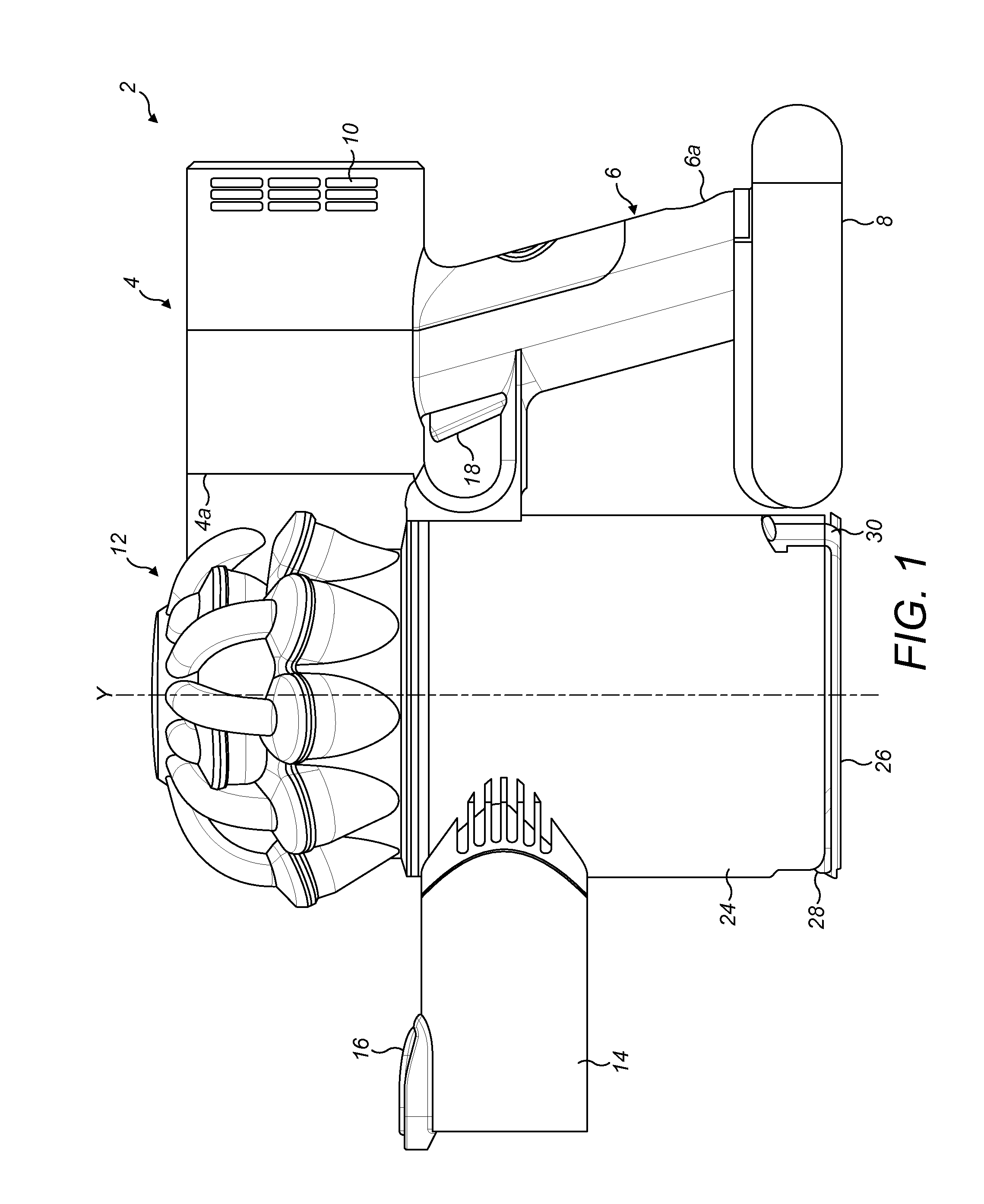
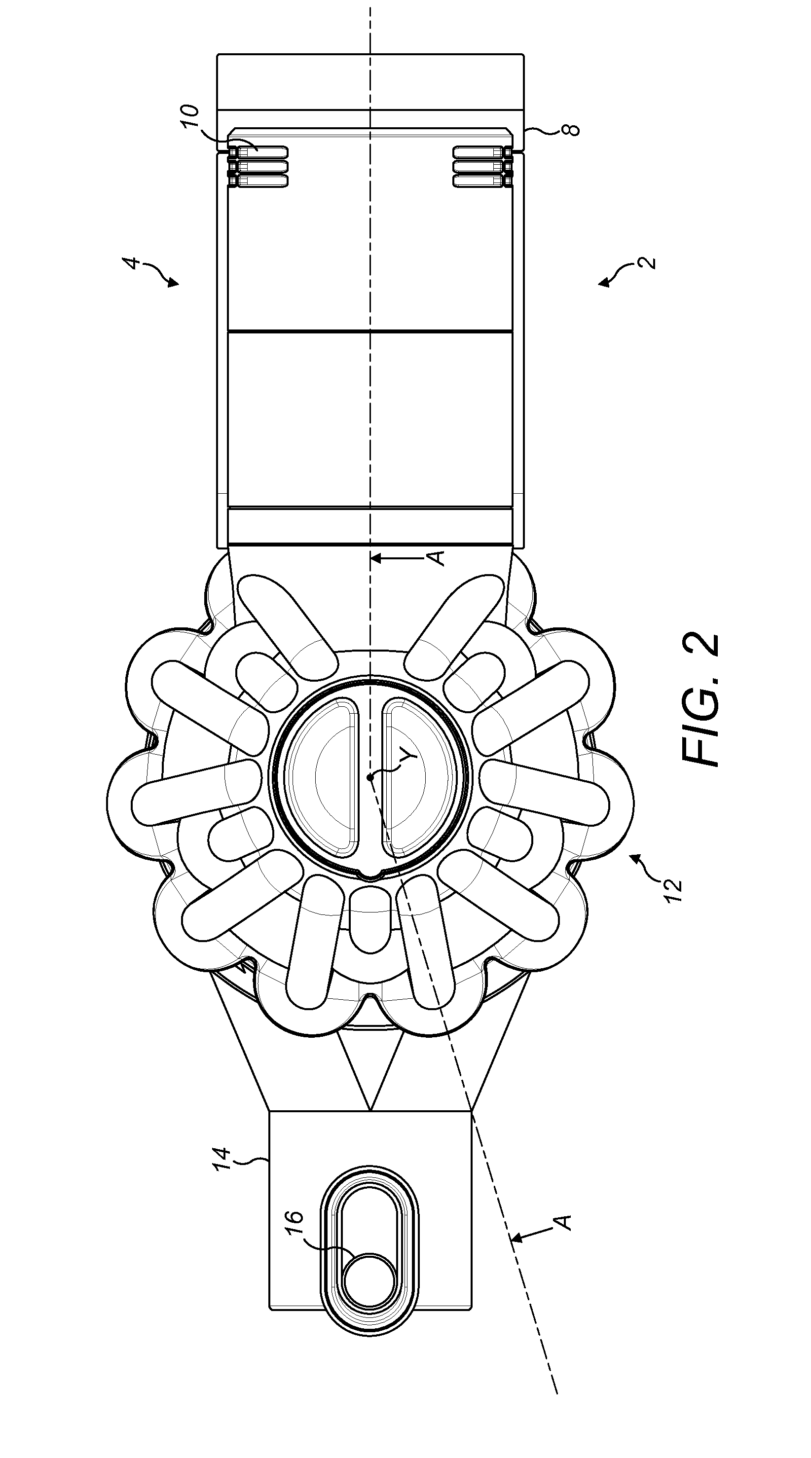
[0029]Referring firstly to FIGS. 1 and 2, a handheld vacuum cleaner 2 has a main body 4 which houses a motor and fan unit (not shown) above a generally upright handle or grip portion 6. The lower end 6a of the handle 6 supports a generally slab-like battery pack 8. A set of exhaust vents 10 are provided on the main body 4 for exhausting air from the handheld vacuum cleaner 2.

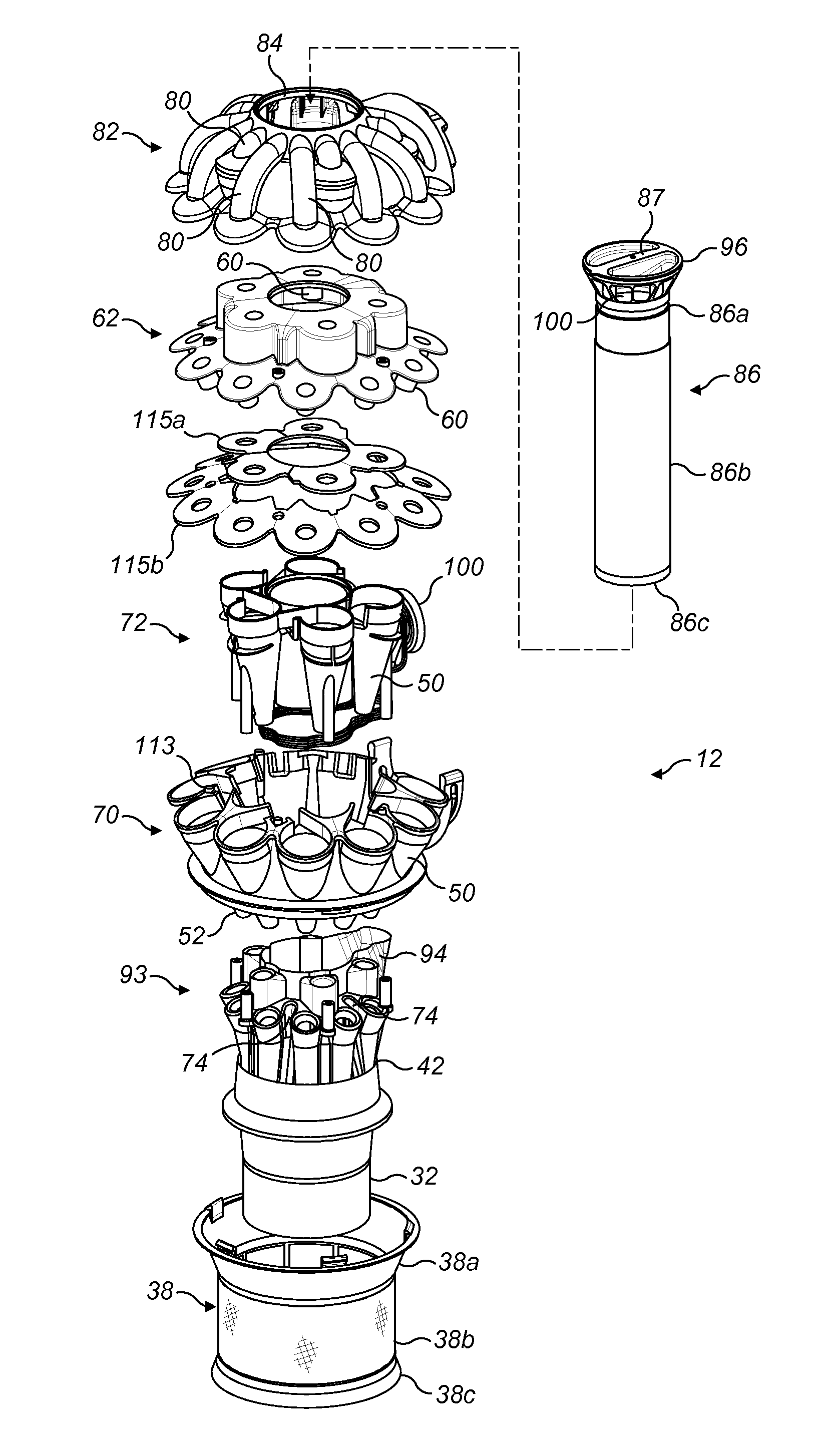
[0030]The main body 4 supports a cyclonic separating apparatus 12 that functions to remove dirt, dust and other debris from a dirt-bearing airflow drawn into the vacuum cleaner by the motor and fan unit. The cyclonic separator 12 is attached to a forward part 4a of the main body 4 and an air inlet nozzle 14 extends from a forward portion of the cyclonic separator that is remote from the main body 4. The air inlet nozzle 14 is configured so that a suitable brush tool can be removably mounted to it and includes a catch 16 for securely holding such a brush tool when the tool is engaged with the inlet. The brush too...


PUM

PropertyMeasurementUnit
Flexibilityaaaaaaaaaa
Circumferenceaaaaaaaaaa

Abstract

A cyclonic separating apparatus comprising a first cyclonic separating unit and, downstream from the first cyclonic separating unit, a second cyclonic separating unit comprising a plurality of cyclones arranged fluidly in parallel about a first axis and a dust collector arranged to receive dust from each of the plurality of cyclones. Each of the plurality of cyclones in the second cyclonic separation unit comprise a fluid inlet and a fluid outlet, the plurality of cyclones being divided into at least a first set of cyclones and a second set of cyclones, the fluid inlets of the first set of cyclones arranged in a first group and the fluid inlets of the second set of cyclones arranged in a second group spaced along said axis from the first group. Each outlet of the plurality of cyclones in the second cyclonic separation unit is provided by a common plate-like vortex finder member.

Description

REFERENCE TO RELATED APPLICATIONS[0001]This application is a national stage application under 35 USC 371 of International Application No. PCT / GB2012 / 053006, filed Dec. 5, 2012, which claims the priority of United Kingdom Application No. 1122161.1, filed Dec. 22, 2011, the entire contents of which are incorporated herein by reference.FIELD OF THE INVENTION[0002]The present invention relates to a cyclonic separating apparatus, and more particularly to a vacuum cleaner equipped with such a cyclonic separating apparatus. In a preferred embodiment, the cyclonic separating apparatus is used in a handheld vacuum cleaner. The invention also relates to a vortex finder plate used in such an apparatus.BACKGROUND OF THE INVENTION[0003]Vacuum cleaners which use cyclonic separating apparatus are well known. Examples of such vacuum cleaners are shown in U.S. Pat. No. 4,373,228, U.S. Pat. No. 3,425,192, U.S. Pat. No. 6,607,572 and EP1268076. The separating apparatus comprises first and second cyclo...

Claims


Application Information

Patent Timeline
IPC IPC(8): A47L9/16
CPCA47L9/1641A47L9/127A47L9/1608A47L9/1625A47L9/1633A47L9/1658A47L9/1666A47L9/1683B01D45/16
Inventor STICKNEY, TIMOTHY NICHOLASLAMBOURN, MICHAEL EDWARD
Owner DYSON TECH LTD
Why Eureka
Try Eureka