Gas-permeable forging mold
A gas-permeable, mold technology, applied in the direction of manufacturing tools, forging/pressing/hammer devices, forging/pressing/hammering machinery, etc., can solve problems such as misalignment, affecting forging accuracy, and materials cannot fill the product cavity, etc., to achieve The effect of preventing dislocation
- Summary
- Abstract
- Description
- Claims
- Application Information
AI Technical Summary
Problems solved by technology
Method used
Image
Examples
Embodiment 1
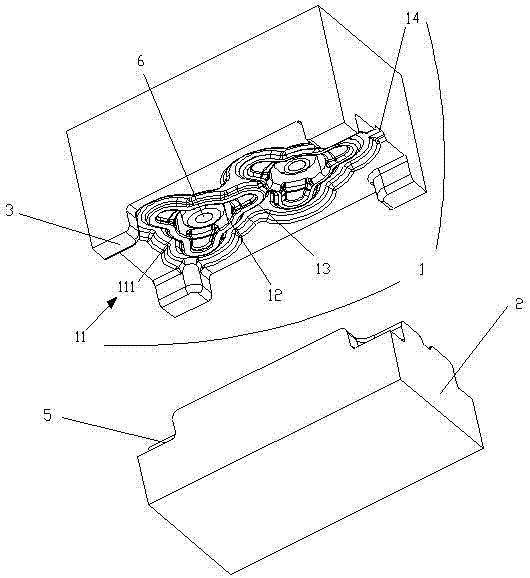
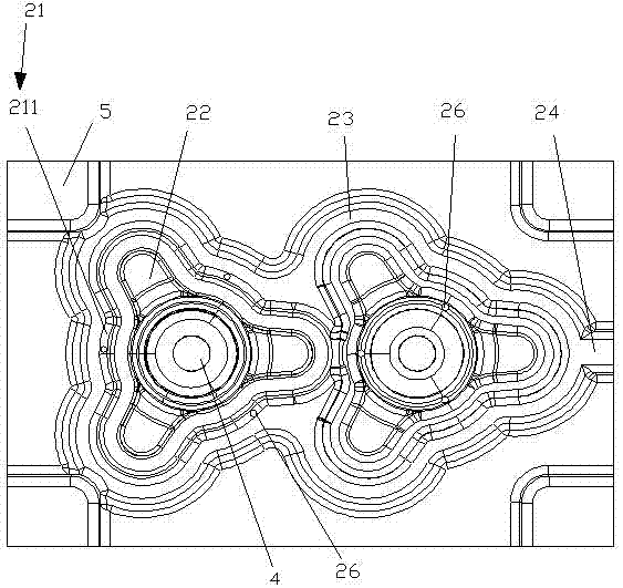
[0019] Such as Figure 1-2 As shown, this embodiment discloses a breathable forging die, which includes an upper die 1 and a lower die 2 that cooperate with each other. Both the bottom of the upper mold 1 and the top of the lower mold 2 are provided with mold cavities. The cavity shapes of the upper mold 1 and the lower mold 2 of the present invention are corresponding.
[0020] The mold cavity of the upper mold 1 includes an upper resistance bridge 11 , an upper product cavity 12 , and an upper flash groove 13 . The upper resistance bridge 11 has a ring structure, an upper product cavity 12 is formed on the inner side, and an upper flash groove 13 is surrounded on the outer side. One or several discontinuous sections of the upper resistance bridge 11 are arched outwards to form an upper fillet structure 111 .
[0021] The mold cavity of the lower mold 2 includes a lower resistance bridge 21 , a lower product cavity 22 , and a lower flash groove 23 . The lower resistance b...
Embodiment 2
[0028] Such as Figure 1-2 As shown, this embodiment discloses a breathable forging die, which includes an upper die 1 and a lower die 2 that cooperate with each other. Both the bottom of the upper mold 1 and the top of the lower mold 2 are provided with mold cavities. The cavity shapes of the upper mold 1 and the lower mold 2 of the present invention are corresponding.
[0029] The mold cavity of the upper mold 1 includes an upper resistance bridge 11 , an upper product cavity 12 , an upper flash groove 13 , and an upper jaw 14 . The upper resistance bridge 11 has a ring structure, an upper product cavity 12 is formed on the inner side, and an upper flash groove 13 is surrounded on the outer side. One or several discontinuous sections of the upper resistance bridge 11 are arched outwards to form an upper fillet structure 111 . An upper jaw 14 is provided on the upper flash groove 13 , and the upper jaw 14 is connected to the edge of the upper mold 1 .
[0030] The mold ca...
Embodiment 3
[0034] Such as Figure 1-2 As shown, this embodiment discloses a breathable forging die, which includes an upper die 1 and a lower die 2 that cooperate with each other. Both the bottom of the upper mold 1 and the top of the lower mold 2 are provided with mold cavities. The cavity shapes of the upper mold 1 and the lower mold 2 of the present invention are corresponding.
[0035] The mold cavity of the upper mold 1 includes an upper resistance bridge 11 , an upper product cavity 12 , an upper flash groove 13 , and an upper jaw 14 . The upper resistance bridge 11 has a ring structure, an upper product cavity 12 is formed on the inner side, and an upper flash groove 13 is surrounded on the outer side. One or several discontinuous sections of the upper resistance bridge 11 are arched outwards to form an upper fillet structure 111 . An upper jaw 14 is provided on the upper flash groove 13 , and the upper jaw 14 is connected to the edge of the upper mold 1 .
[0036] The mold ca...
PUM
 Abstract
Description
Claims
Application Information
 - R&D
- Intellectual Property
- Life Sciences
- Materials
- Tech Scout
- Unparalleled Data Quality
- Higher Quality Content
- 60% Fewer Hallucinations
Browse by: Latest US Patents, China's latest patents, Technical Efficacy Thesaurus, Application Domain, Technology Topic, Popular Technical Reports.
© 2025 PatSnap. All rights reserved.Legal|Privacy policy|Modern Slavery Act Transparency Statement|Sitemap|About US| Contact US: help@patsnap.com


