Locking mechanism of electronic coded lock

An electronic combination lock and locking mechanism technology, applied in the field of electronic combination locks, can solve the problems of low opening and closing sensitivity, unreasonable internal structure design, and low safety performance of the combination lock, and achieve fast action, high accuracy, and safety performance. high effect

Active Publication Date: 2017-06-20
东莞东晟装备科技有限公司
View PDF7 Cites 0 Cited by
  • Summary
  • Abstract
  • Description
  • Claims
  • Application Information

AI Technical Summary

Problems solved by technology

[0002] The problem of property and information security has always been a problem that all walks of life attach great importance to, so the application of locks is ubiquitous, but traditional locks need to carry keys with them, which brings a lot of inconvenience, while combination locks are receiving more and more attention because they do not need keys. Loved and used by people
However, due to the unreasonable design of the internal structure of the traditional combination lock mechanism, the sensitivity of opening and closing of the combination lock is low, it is prone to failure, it is inconvenient to use, it is not practical, and its safety performance is low.

Method used


Image

  • Locking mechanism of electronic coded lock
  • Locking mechanism of electronic coded lock
  • Locking mechanism of electronic coded lock

Examples


Embodiment Construction

[0027] In order to further illustrate the technical means and functions adopted by the present invention to achieve the intended purpose, the specific implementation modes of the present invention will be described in detail below in conjunction with the accompanying drawings and preferred embodiments.

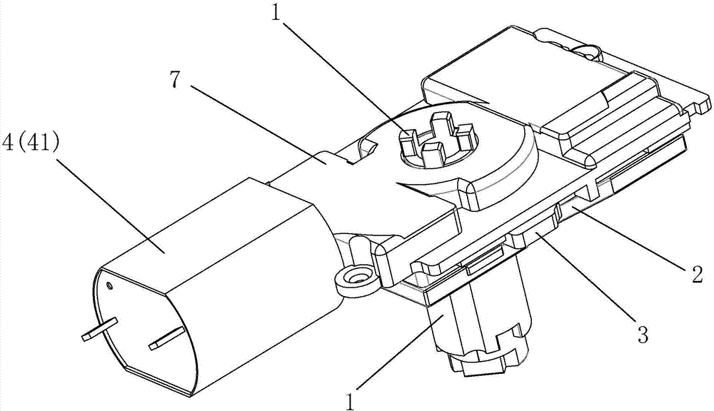
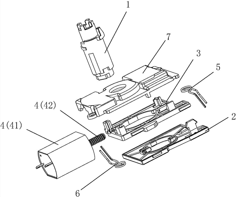
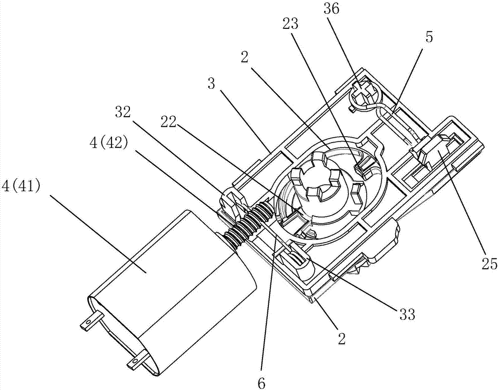
[0028] Please refer to Figure 1 to Figure 11 , the embodiment of the present invention provides an electronic combination lock locking mechanism, including a lock cylinder 1, a small lock cylinder opening and closing slider 2 and a lock cylinder limit slider 3 that are sleeved on the outside of the lock cylinder 1 and stacked from bottom to top. , and the drive assembly 4 connected with the lock cylinder limit slider 3, wherein the drive assembly 4 includes a motor 41, and a motor transmission threaded shaft sleeve 42 arranged at one end of the motor 41, the motor transmission threaded shaft 42 sleeve is located at Above the small slider 3 for limiting the lock cylinder; the ...


PUM


Abstract

The invention discloses a locking mechanism of an electronic coded lock. The locking mechanism comprises a lock cylinder, a small lock cylinder unlocking / locking slide block, a small lock cylinder limiting slide block and a driving assembly; the driving assembly comprises a motor and a motor driving screw shaft sleeve which is located above the small lock cylinder limiting slide block; a through hole for penetrating the lock cylinder is formed in the small lock cylinder unlocking / locking slide block, and the inner wall of the through hole is convexly provided with a locking piece and a convex block towards the inner side; a clamping slot for clamping the locking piece is formed in one side surface of the lock cylinder, and a stop block is arranged on the other side surface opposite to the one side surface; the small lock cylinder limiting slide block covers the small lock cylinder unlocking / locking slide block and is provided with a reset spring and a slide block driving spring, and the slide block driving spring is clamped on a tooth position of the motor driving screw shaft sleeve; and a driving insertion hole is formed in the small lock cylinder unlocking / locking slide block, and the lower end of the small lock cylinder limiting slide block is provided with a driving block inserted into the driving insertion hole. The locking mechanism realizes the locking and unlocking functions of the coded lock and is high in action speed, precise, flexible, high in stability, safety performance and practicability.

Description

technical field [0001] The invention relates to the field of electronic combination locks, in particular to an electronic combination lock locking mechanism. Background technique [0002] The problem of property and information security has always been a problem that all walks of life attach great importance to, so the application of locks is ubiquitous, but traditional locks need to carry keys with them, which brings a lot of inconvenience, while combination locks are receiving more and more attention because they do not need keys. Loved and used by people. From traditional cabinet code locks to rope-type code locks for computer applications, code locks are rapidly being used in more and more applications, such as lockers, logistics cabinets, safes, etc. [0003] The most important component in the combination lock is the locking mechanism, and the rationality of the structural design of the locking mechanism directly determines the flexibility and safety of the combinatio...

Claims


Application Information

Patent Timeline
Patent Type & Authority Applications(China)
IPC IPC(8): E05B47/00E05B49/00E05B15/00
CPCE05B15/00E05B47/0012E05B49/00
Inventor 陈波
Owner 东莞东晟装备科技有限公司
Why Eureka
Try Eureka