Pipeline fixing structure

A technology for fixing structures and pipelines, applied to pipeline supports, pipes/pipe joints/fittings, mechanical equipment, etc., can solve problems such as increasing the cost of pipeline construction, and achieve the effect of saving time in setting

Active Publication Date: 2017-06-20
TAIWAN PAIHO LTD
View PDF11 Cites 0 Cited by
  • Summary
  • Abstract
  • Description
  • Claims
  • Application Information

AI Technical Summary

Problems solved by technology

However, although this structure retains the changeability of the location of the pipeline, it requires the use of specially designed pipelines, which greatly increases the cost of pipeline construction.

Method used


Image

  • Pipeline fixing structure
  • Pipeline fixing structure
  • Pipeline fixing structure

Examples


Embodiment Construction

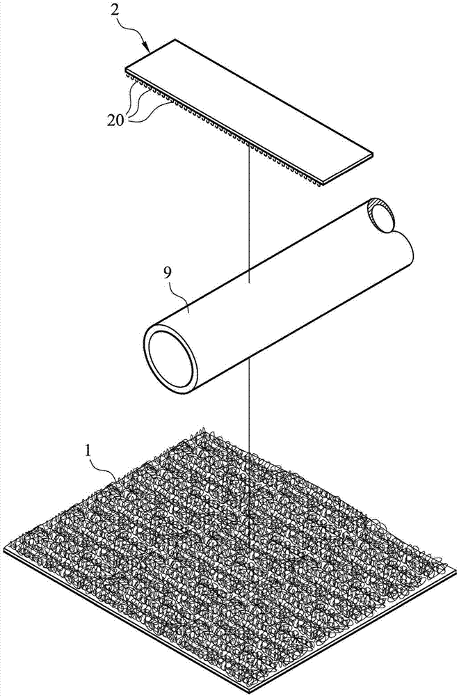
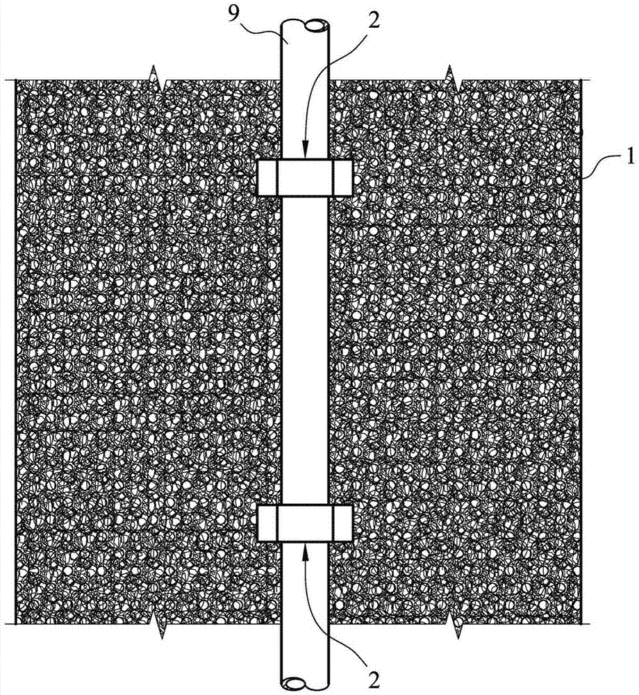
[0043] Figure 1 to Figure 3 A piping fixing structure according to a first embodiment of the present invention is shown.

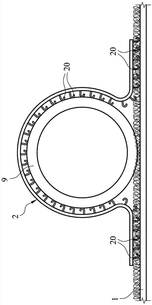
[0044] Such as figure 1 As shown, the pipeline fixing structure according to the first embodiment of the present invention includes a substrate layer 1 and a fixing member 2 . The substrate layer 1 has a matte surface. The fixing member 2 is provided with a plurality of hooks 20 on one surface (first surface), and the hooks 20 can be mechanically fastened to the rough surface of the substrate layer 1 .

[0045] Next, the case of fixing the pipeline 9 in the floor heating system by means of the pipeline fixing structure according to the first embodiment of the present invention will be described. Firstly, the base material layer 1 is laid (fixed) on the ground in the predetermined range where the floor heating system is to be installed, and the pipeline 9 to be installed is placed on the base material layer 1 . Then, the central section of the fixing p...


PUM


Abstract

The invention relates to a pipeline fixing structure used for fixing a pipeline in a floor heating system. The pipeline fixing structure comprises a substrate layer and one or more fixing pieces, wherein the substrate layer is fixed on the ground and is provided with a hair surface; a plurality of hook bodies which can be mechanically fastened on the hair surface of the substrate layer are arranged on the first surface of each fixing piece; and each fixing piece is configured in the manner that after the pipeline is placed on the substrate layer, each fixing piece is used for fixing the pipeline through the mechanical fastening between the hook bodies and the substrate layer in the manner of surrounding the pipeline.

Description

technical field [0001] The invention relates to a pipeline fixing structure for fixing pipelines in a floor heating system, in particular to a pipeline fixing structure for fixing pipelines through the cooperation of a rough surface and a hook body. Background technique [0002] In order to enable people to have a more comfortable indoor environment, floor heating systems for adjusting the temperature of the ground are buried in the ground in some buildings, and the floor heating system is mainly operated by pipelines arranged in the ground. [0003] In the known floor heating systems, as disclosed in US Pat. No. 6,969,832B1, US 7,145,112B1, etc., in order to fix the pipeline in the ground, the pipeline is generally clamped on the metal mesh by clamps first, and the The metal mesh and the pipeline are laid within the predetermined range, and finally the grouting procedure is carried out to complete the fixing of the pipeline. However, if the pipelines in the floor heating s...

Claims


Application Information

Patent Timeline
IPC IPC(8): F16L3/10
CPCF16L3/1025F16L3/1075F16L3/1091
Inventor 郑诚祎
Owner TAIWAN PAIHO LTD
Why Eureka
Try Eureka