LED light device

An LED lamp device and LED lamp technology, applied in the field of lighting, can solve problems such as limited length of power supply lines, damage and scratches of power supply lines, and achieve the effects of improving service life and safety, preventing too many plug-in points, and convenient operation

Active Publication Date: 2017-12-19
盐城明钰科技有限公司
View PDF5 Cites 0 Cited by
  • Summary
  • Abstract
  • Description
  • Claims
  • Application Information

AI Technical Summary

Problems solved by technology

[0002] LED lamps have gradually replaced the existing incandescent lamps and fluorescent lamps and become the lighting equipment used on the stage of a new generation of weddings and evening parties. It can be plugged in. However, due to the limited length of the power supply line of the LED lamp, in some special occasions, the LED lamp is placed far away and needs to be extended and connected through one or more wiring boards to achieve the ideal power supply plug-in length. However, the wiring The power supply line of the board has a certain length, which is extremely inconvenient when retracting and unfolding, and the power supply line is thrown on the ground at will during the power supply process, so that the power supply line is vulnerable to various accidental damages, such as people stepping on it, scratching by hard objects, etc., resulting in power supply failure. The insulation skin on the outside of the line is damaged, resulting in a decrease in the service life of the power supply line; at the same time, because there are many plug-in points when connecting multiple terminal boards, there is a possibility of inducing an electric shock when accidentally touched by humans, and there is a great potential safety hazard

Method used


Image

  • LED light device
  • LED light device
  • LED light device

Examples


Embodiment Construction

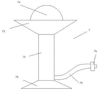
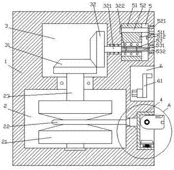
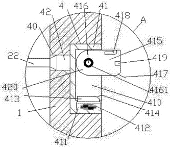
[0022] like Figure 1-Figure 7 As shown in the figure, an LED lamp device of the present invention includes an LED lamp 7 and a power distribution base 1 that is cooperatively connected with the LED lamp 7 . The power distribution base 1 is provided with a first empty slot 3, and the power distribution base 1 on the right side of the first empty slot 3 is provided with a second empty slot 5. The outer side wall of the power distribution base 1 is provided with a placement slot 4 , and the outer side wall of the power distribution base 1 above the placement slot 4 is provided with a storage slot 6 . There is a through slot 40, and a steering shaft 23 extending up and down is arranged in the container 2. The upward extending section of the steering shaft 23 penetrates the inner wall of the power distribution base 1 and is connected with the steering, and the top of the steering shaft 23 extends with a tip. A first toothed plate 31 is fixedly inserted into the first hollow slot ...


PUM


Abstract

The invention discloses an LED lamp device which comprises an LED lamp and a power distribution base body matched and connected with the LED lamp. A containing bin is arranged in the power distribution base body, and a first empty groove is formed in the position, above the containing bin, in the power distribution base body. A second empty groove is formed in the position, on the right side of the first empty groove, in the power distribution base body. A containing groove is formed in the position, on the right side of the containing bin, in the outer side wall of the power distribution base body. A storage groove is formed in the position, above the containing groove, in the outer side wall of the power distribution base body. A through groove is formed between the containing groove and the containing bin. A steering shaft extending vertically is arranged in the containing bin, an upward extending section of the steering shaft penetrates the inner wall of the power distribution base body and is in steering fit connection with the inner wall of the power distribution base body. A top extending tail end of the steering shaft penetrates in the first empty groove and is fixedly provided with a first tooth plate, and a second tooth plate is matched and connected with the upper side of the right side of the first tooth plate. The right side of the second tooth plate is fixedly provided with a transmission shaft extending towards the right side, a right side extending section of the transmission shaft penetrates the wall of the power distribution base body and is in steering fit connection with the wall of the power distribution base body, and a right side extending tail end of the transmission shaft is provided with a first outer spline shaft penetrating in the second empty groove. The LED lamp device is simple in structure, convenient to operate, capable of meeting the requirement for long-distance power supply plug connection and achieving automatic wire collecting work and high in safety.

Description

technical field [0001] The invention relates to the technical field of lighting, in particular to an LED lamp device. Background technique [0002] LED lamps have gradually replaced the existing incandescent lamps and fluorescent lamps and become the lighting equipment used on the stage of a new generation of weddings and parties. It can be plugged in. However, due to the limited length of the power supply line of the LED lamp, in some special occasions, the LED lamp is placed farther away and needs to be connected through one or more wiring boards to reach the ideal power supply plugging length. However, the wiring The power supply line of the board has a certain length, which is extremely inconvenient when retracting, and the power supply line is randomly thrown on the ground during the power supply process, so that the power supply line is vulnerable to various accidental damages, such as people stepping on, scratches on hard objects, etc., resulting in power supply. The...

Claims


Application Information

Patent Timeline
Patent Type & Authority Patents(China)
IPC IPC(8): F21V27/00F21Y115/10
CPCF21V27/00
Inventor 王杏文王明郑竹琴
Owner 盐城明钰科技有限公司
Why Eureka
Try Eureka