A manually controlled charging device for new energy vehicles

A technology for new energy vehicles and charging equipment, which is applied in the direction of electric vehicle charging technology, electric vehicles, charging stations, etc., and can solve problems such as cable life reduction, people trampling, vehicle rolling, electric shock, etc., to prevent electric shock accidents and improve usage The effect of life and safety

Inactive Publication Date: 2018-06-01
深圳奇速新能源科技有限公司
View PDF5 Cites 0 Cited by
  • Summary
  • Abstract
  • Description
  • Claims
  • Application Information

AI Technical Summary

Problems solved by technology

The charging pile is an important basic supporting charging facility for electric vehicles. The use of the charging pile is very similar to the refueling process of the car. After connecting and charging, the operator should arrange the charging cable and put the charging gun head back to the charging pile. However, users often throw the cable on the ground after using it; in this way, the cable is vulnerable to various accidents. Stress, such as trampling by people, rolling by cars, etc., will cause damage to the outer insulation of the cable, resulting in a decrease in the life of the cable; because the cable is an unsafe voltage, once the insulation is damaged, there will be safety hazards such as abnormal insulation, and if it is not found in time, it will cause electric shock. In addition, some existing charging piles with automatic take-up devices need to be powered by electricity, resulting in a waste of power resources, and the traditional charging tip without protection measures is likely to cause damage to the tip

Method used


Image

  • A manually controlled charging device for new energy vehicles
  • A manually controlled charging device for new energy vehicles
  • A manually controlled charging device for new energy vehicles

Examples


Embodiment Construction

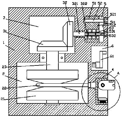
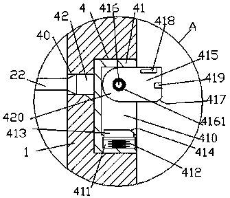
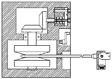
[0023] Such as Figure 1-Figure 7 As shown, a manually controlled new energy vehicle charging device of the present invention includes a pile body 1, and a storage cavity 2 is arranged inside the pile body 1, and a first A cavity 3, the pile body 1 on the right side of the first cavity 3 is provided with a second cavity 5, and the outside wall of the pile body 1 on the right side of the storage cavity 2 is provided with a receiving groove 4. A storage tank 6 is provided in the outer wall of the pile body 1 above the installation groove 4, and a communication hole 40 is provided between the installation groove 4 and the storage cavity 2, and the storage cavity 2 A rotating shaft 23 extending up and down is provided. The upward extending section of the rotating shaft 23 penetrates the inner wall of the pile body 1 and is connected in a rotational fit. The top extension end of the rotating shaft 23 extends into the first cavity 3 and is fixed. A first conical wheel 31 is provide...


PUM


Abstract

The invention discloses a manually controlled charging device for new energy vehicles (NEVs) comprising a pile body, wherein a storage cavity is arranged in the pile body; a first cavity is arranged in the pile body and above the storage cavity; a second cavity is arranged in the pile body and on the right side of the first cavity; a mounting and inserting groove is arranged at the outer side wall, on the right side of the storage cavity, of the pile body; a storing groove is arranged at the outer side wall, above the mounting and inserting groove, of the pile body; a communicating hole is arranged between the mounting and inserting groove and the storing cavity; a rotating shaft extending upwards and downwards is arranged in the storage cavity; the upward extending section of the rotating shaft runs through the inner wall of the pile body and is rotatably connected with the inner wall of the pile body; the top extending end of the rotating shaft stretches into the first cavity and is fixedly provided with a first bevel gear; a second bevel gear is engaged with the upper right part of the first bevel gear; a transmission shaft extending rightwards is fixedly arranged at the right side of the second bevel gear; the rightward extending section of the transmission shaft runs through the wall body of the pile body and is rotatably connected with the wall body of the pile body; and the rightward extending end of the transmission shaft stretches into a first outer spline shaft in the second cavity. The manually controlled charging device for the NEVs has the advantages of simple structure, convenient operation, low manufacturing cost and high safety.

Description

technical field [0001] The invention relates to the technical field of new energy vehicle charging, in particular to a manually controlled charging device for new energy vehicles. Background technique [0002] In recent years, the problem of urban environmental pollution has become more and more serious, among which automobile exhaust pollution is increasingly endangering people's health. With the improvement of environmental protection awareness, the rapid development of low-carbon economy and energy-saving emission reduction technology, electric vehicles have The advantages of pollution have begun to be popularized and applied in daily life. The charging pile is an important basic supporting charging facility for electric vehicles. The use of the charging pile is very similar to the refueling process of the car. After connecting and charging, the operator should arrange the charging cable and put the charging gun head back to the charging pile. However, users often throw ...

Claims


Application Information

Patent Timeline
Patent Type & Authority Patents(China)
IPC IPC(8): B60L11/18
CPCB60L53/16B60L53/31Y02T10/70Y02T10/7072Y02T90/12Y02T90/14
Inventor 梁敏华
Owner 深圳奇速新能源科技有限公司
Why Eureka
Try Eureka