Convenient-to-operate bridge device

A technology of equipment and bridges, which is applied in the field of bridge equipment that is easy to control, can solve problems such as damaged insulation of power supply lines, inconvenient retractable wiring boards, and reduced service life of power supply lines, so as to prevent electric shock accidents, improve service life and safety , the effect of convenient operation

Inactive Publication Date: 2018-06-29
PUJIANG FEITONG ELECTRONICS TECH CO LTD
View PDF0 Cites 0 Cited by
  • Summary
  • Abstract
  • Description
  • Claims
  • Application Information

AI Technical Summary

Problems solved by technology

[0002] Electrified maintenance equipment is often used in the bridge maintenance process. However, in some bridge constructions, there are fewer preset power supply seats and they are all fixed. This makes it difficult to connect the power supply. In the prior art, one or more terminal boards are generally used to lengthen the connection to reach the ideal power supply plug-in length. Throw the power supply line on the ground, so that the...

Method used


Image

  • Convenient-to-operate bridge device
  • Convenient-to-operate bridge device
  • Convenient-to-operate bridge device

Examples


Embodiment Construction

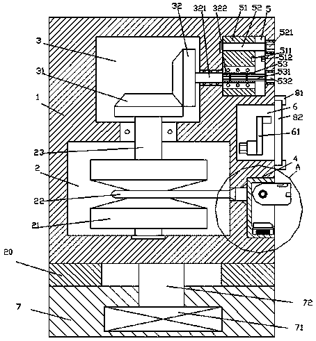
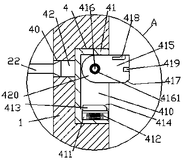
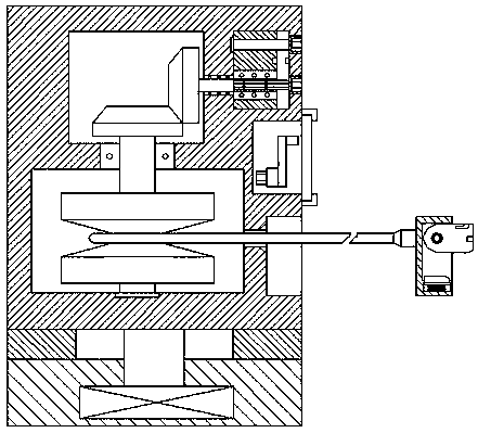
[0024] Such as Figure 1-Figure 7 As shown, a bridge device that is easy to handle in the present invention includes a base 7 and a machine body 1 arranged above the base 7 , a driving device 71 is provided at the inner bottom of the base 7 , and a driving device 71 is arranged on the top of the driving device 71 . A rotating column 72 is connected, and the extended end of the top of the rotating column 72 penetrates the inner wall of the base 7 and is fixedly connected with the bottom end surface of the body 1. A bearing 10 is arranged between the body 1 and the base 7, so that The body 1 is provided with a cavity 2, the body 1 above the cavity 2 is provided with a first horizontal cavity 3, and the body 1 on the right side of the first horizontal cavity 3 is provided with a second horizontal cavity. Cavity 5, the outer wall of the body 1 on the right side of the cavity 2 is provided with an installation groove 4, and the outer wall of the body 1 above the installation groove...


PUM


Abstract

The invention discloses a convenient-to-operate bridge device. The device comprises a base and a machine body arranged on the base; a driving device is arranged in the base; the top of the driving device is connected with a rotation column; the extending end of the top of the rotation column penetrates the inner wall of the base and is fixedly connected with the end surface of the bottom of the machine body; a bearing is arranged between the machine body and the base; an accommodating cavity is defined in the machine body; a first horizontal cavity located above the accommodating cavity is defined in the machine body; a second horizontal cavity located on the right side of the first horizontal cavity is defined in the machine body; an installation groove located on the right side of the accommodating cavity is formed in the outer side wall of the machine body; a storage groove located above the installation groove is formed in the outer side wall of the machine body; a communication hole is formed between the installation groove and the accommodating cavity; a rotation shaft which can extend upwards and downwards is arranged in the accommodating cavity; the upwards-extending section of the rotation shaft penetrates the inner wall of the machine body and is in rotary and matched connection with the inner wall of the machine body; the extending tail end of the top of the rotationshaft extends into the first horizontal cavity and is fixedly provided with a first gear; the upper part of the right side of the first gear is in meshed connection with a second gear; the right sideof the second gear is fixedly provided with a force transmission shaft extending rightwards; the extending section of the right side of the force transmission shaft penetrates the wall body of the machine body and is in rotary and matched connection with the wall body; and the extending tail end of the right side of the force transmission shaft is provided with a first bearing entering the secondhorizontal cavity. The convenient-to-operate bridge device of the invention is simple in structure and convenient to operation. With the device adopted, automatic wire collection can be realized, andthe security of power supply plugging can be improved.

Description

technical field [0001] The invention relates to the technical field of bridge facilities, in particular to bridge equipment that is easy to handle. Background technique [0002] Electrified maintenance equipment is often used in the bridge maintenance process. However, in some bridge constructions, there are fewer preset power supply seats and they are all fixed. This makes it difficult to connect the power supply. In the prior art, one or more terminal boards are generally used to lengthen the connection to reach the ideal power supply plug-in length. Throw the power supply line on the ground, so that the power supply line is vulnerable to various accidental damages, such as trampling by people, rolling over by cars, etc., which will cause damage to the outer insulation of the power supply line and reduce the life of the power supply line; at the same time, due to multiple terminal boards There are many plug-in points during connection, and there is a possibility of induci...

Claims


Application Information

Patent Timeline
IPC IPC(8): H01R13/72H01R13/44E01D22/00
CPCH01R13/72E01D22/00H01R13/44
Inventor 吕华
Owner PUJIANG FEITONG ELECTRONICS TECH CO LTD
Why Eureka
Try Eureka