
Quick connector for power control equipment

A power control and connector technology, applied in conductive connections, electrical component connections, multi-conductor connectors, etc., can solve the problems of poor wiring quality, low work efficiency, inconvenient operation, etc., to ensure wiring quality and improve work efficiency. Effect

Active Publication Date: 2018-12-28
SKILL TRAINING CENT STATE GRID JIBEI ELECTRONICS POWER COMPANY +1
View PDF6 Cites 0 Cited by
  • Summary
  • Abstract
  • Description
  • Claims
  • Application Information

AI Technical Summary

Problems solved by technology

However, this kind of wiring method is not only very inconvenient to operate, low in work efficiency, but also poor in wiring quality in a narrow space or in a high-altitude working environment.

Method used


Image

  • Quick connector for power control equipment
  • Quick connector for power control equipment
  • Quick connector for power control equipment

Examples


Embodiment Construction

[0023] The present invention will be further described in detail below in conjunction with the accompanying drawings and specific embodiments.

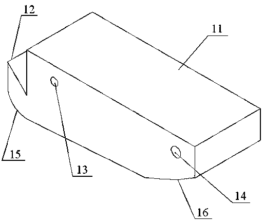
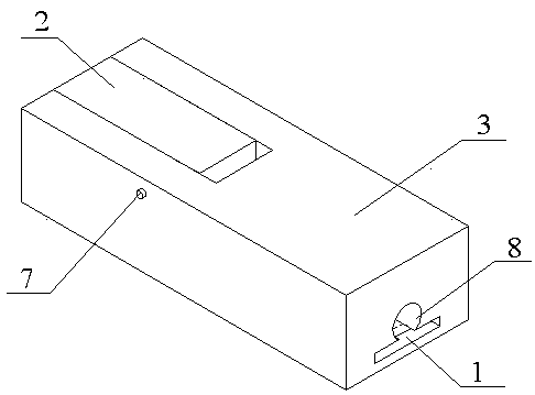
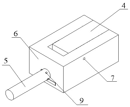
[0024] A quick connector for power control equipment, the structure of which is as follows Figure 2 to Figure 5 As shown, it includes a matching concave component and a convex component. The concave component and the convex component respectively destroy the insulation of the two wires and connect the two together, which is very convenient.

[0025] The structure of the convex component is as image 3 As shown, it includes a male component housing 6, and a through hole is provided in the axial direction of the male component housing, and a conductive plate communicating with the through hole is embedded in the male component housing 6; the through hole at one end of the female component is matched A conductive core 5 is arranged inside, and the conductive core 5 extends out of the shell of the male component, and the conductive core...


PUM


Abstract

The invention discloses a rapid wire connector used for electric control equipment. The rapid wire connector comprises a concave assembly and a convex assembly which are assembled, wherein the convex assembly comprises a convex assembly shell, a first cut-through through hole is formed in the axial direction of the convex assembly shell, and a conducting wore stretching out of the convex assembly shell is formed inside the through hole; a first square groove is formed in the upper part of the convex assembly shell, and a second wire connection pressing block is articulated inside the first square groove; the concave assembly comprises a concave assembly shell, a second cut-through through hole is formed in the axial direction of the concave assembly shell, and a conducting plate communicating with the second through hole is embedded in the concave assembly shell; a second square groove is formed in the upper part of the concave assembly shell, and a first wire connection pressing block is articulated inside the second square groove; and the conducting core of the convex assembly is assembled with the through hole of the concave assembly. The rapid wire connector is applied to the electric control equipment in the maintenance process, exposed lead ends can be rapidly treated, the problem that wire connection is inconvenient in narrow and small spaces or at high places is solved, the wire connection quality is guaranteed, and the work efficiency is improved.

Description

technical field [0001] The invention relates to the technical field of electric control equipment maintenance, in particular to a wiring device used in the process of electric work. Background technique [0002] In the process of power system maintenance, it is often necessary to carry out the wiring operation of wires. For example, in the process of maintaining power control equipment, it is necessary to find and repair the fault location of power control equipment, and there are many complicated wiring in power control equipment, and These wirings are often located inside the equipment. Due to the narrow space, wiring operations are difficult; for another example, for the ammeter and transformer at the upper end of the pole, wiring and other operations are also required during maintenance. [0003] At present, the wiring operation is mainly through the steps of using tools to peel off the insulating sheath of the wires, then manually connecting the two wires, and finally w...

Claims


Application Information

Patent Timeline
Patent Type & Authority Patents(China)
IPC IPC(8): H01R11/01H01R11/03
CPCH01R11/01H01R11/03
Inventor 葛林陈金辉张晓东
Owner SKILL TRAINING CENT STATE GRID JIBEI ELECTRONICS POWER COMPANY
Learn More