Cable bending fixing structure

A technology for fixing structures and cables, applied in the direction of cable installation, cable installation devices, electrical components, etc., to achieve the effect of a wide range of use

Inactive Publication Date: 2017-06-20
CHENGDU FEIHANG PEIPENG TECH CO LTD
View PDF9 Cites 1 Cited by
  • Summary
  • Abstract
  • Description
  • Claims
  • Application Information

AI Technical Summary

Problems solved by technology

[0003] The purpose of the present invention is to solve the shortcomings of the limitation of the cable bending and fixing structure in the prior art, and propose a cable bending and fixing structure

Method used


Image

  • Cable bending fixing structure
  • Cable bending fixing structure

Examples


Embodiment Construction

[0013] The technical solutions in the embodiments of the present invention will be clearly and completely described below in conjunction with the accompanying drawings in the embodiments of the present invention. Obviously, the described embodiments are only a part of the embodiments of the present invention, rather than all the embodiments.

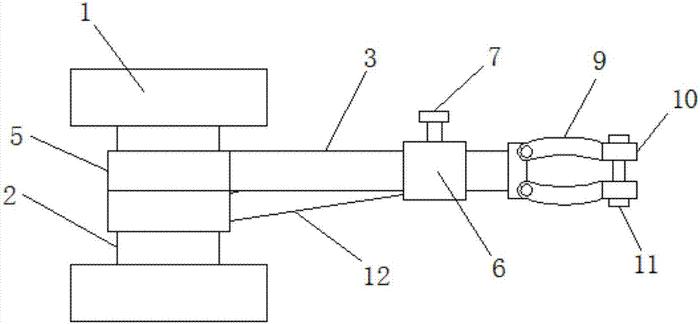
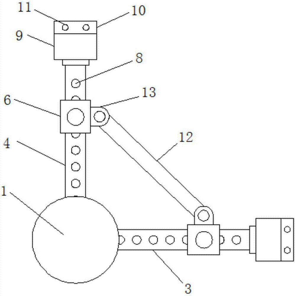
[0014] Reference Figure 1-2 , A cable bending and fixing structure, including a fixed shaft 2, two ends of the fixed shaft 2 are fixedly connected with a mounting base 1, the mounting base 1 is arranged in a circular shape, and the mounting base 1 is evenly provided with a plurality of convenient fixing The mounting hole is convenient for installing the fixed structure of the cable, which makes the fixing of the cable more stable. Two shaft sleeves 5 are sleeved on the fixed shaft 2, and the two shaft sleeves 5 are respectively fixedly connected with the horizontal first movable arm 3 and The upper ends of the second movable arm 4, the fir...


PUM


Abstract

The invention relates to the technical field of electric power transmission, in particular to a cable bending fixing structure. The fixing structure comprises a fixed shaft. Multiple limiting holes are arranged in the upper end of a first moving arm and the upper end of a second moving arm. Each of the first moving arm and the second moving arm is sleeved in a sleeve. Connection lugs are arranged on the sleeves. A support rod is movably connected between the connection lugs. Upper ends of the sleeves are in threaded connection with fixing screw rods which are in threaded connection with the limiting holes. End parts of the first moving arm and the second moving arm are movably connected with two symmetrically arranged clamp plates. End parts of the clamp parts are connected with connection plates. A locking screw is connected between the connection plates. According to the invention, bending degree of a cable can be adjusted according to working tasks; use range of the fixing structure is allowed to be quite large; and the fixing structure is suitable for working under all kinds of the installation tasks.

Description

Technical field [0001] The present invention relates to the technical field of power transmission, in particular to a cable bending and fixing structure. Background technique [0002] In the process of installing cables, it is often necessary to bend the cables. The bending angle of the traditional cable bending and fixing structure is fixed, and the bending angle of the cable cannot be adjusted according to the size of the installation space. This makes the use of the cable bending and fixing structure limited and cannot be adapted to each For this purpose, we propose a cable bending and fixing structure. Summary of the invention [0003] The purpose of the present invention is to solve the limitation of the cable bending and fixing structure in the prior art, and proposes a cable bending and fixing structure. [0004] In order to achieve the above objectives, the present invention adopts the following technical solutions: [0005] A cable bending and fixing structure is designed, ...

Claims


Application Information

Patent Timeline
Patent Type & Authority Applications(China)
IPC IPC(8): H02G1/00B21F1/00
CPCH02G1/00B21F1/002
Inventor 李丹
Owner CHENGDU FEIHANG PEIPENG TECH CO LTD
Why Eureka
Try Eureka