Clamp-driven integrated type piezoelectric-drive high-precision rotary actuator and method thereof

A rotary actuation and piezoelectric drive technology, applied in the direction of piezoelectric effect/electrostrictive or magnetostrictive motors, electrical components, generators/motors, etc., can solve the problem of output, The problem of small actuating stroke achieves the effect of low standby power consumption, large axial load and easy realization

Active Publication Date: 2017-06-23
西安朗威科技有限公司
View PDF5 Cites 6 Cited by
  • Summary
  • Abstract
  • Description
  • Claims
  • Application Information

AI Technical Summary

Problems solved by technology

[0002] In recent years, the continuous development of piezoelectric actuators has supported the development and construction of important industries such as national defense, aerospace, and machinery manufacturing, and has also derived a wide variety of piezoelectric actuators. However, due to the shortcomings of piezoelectric materials with small actuating strokes, On the one hand, it is difficult for piezoelectric ceramic actuators to achieve large strokes, especially the output of large rotational angle displacements. On the other hand, it also puts forward higher requirements for processing and assembly.

Method used


Image

  • Clamp-driven integrated type piezoelectric-drive high-precision rotary actuator and method thereof
  • Clamp-driven integrated type piezoelectric-drive high-precision rotary actuator and method thereof
  • Clamp-driven integrated type piezoelectric-drive high-precision rotary actuator and method thereof

Examples


Embodiment Construction

[0021] The present invention will be further described in detail below with reference to the drawings and specific embodiments.

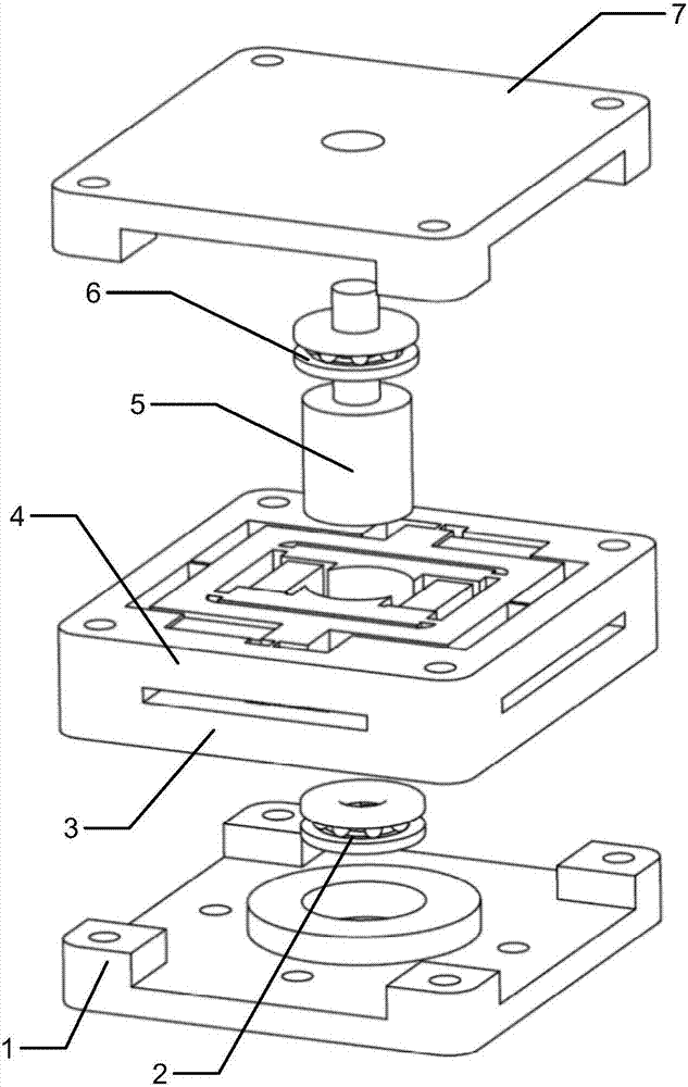
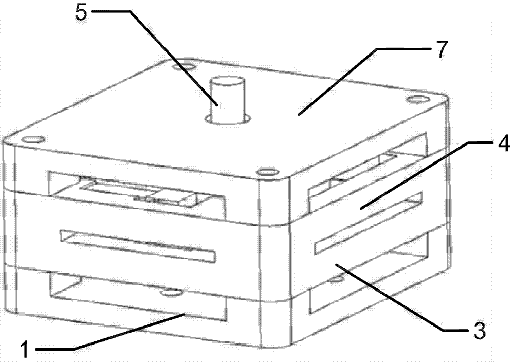
[0022] Such as figure 1 with figure 2 As shown, a piezoelectric drive high-precision rotary actuator with integrated clamp drive of the present invention includes an actuator base 1, mounted on the base 1, and a lower thrust ball bearing 2 that can bear axial load. The lower drive structure 3 above the base 1, the upper drive structure 4 integrated with the lower drive structure 3, is mounted on the lower thrust ball bearing 2 and can be clamped and controlled by the lower drive structure 3 and the upper drive structure 4 output shaft 5 , The upper thrust ball bearing 6 is installed above the output shaft 5, the top cover 7 is installed above the thrust ball bearing, and the top cover 7 is extended from the top of the output shaft 5.

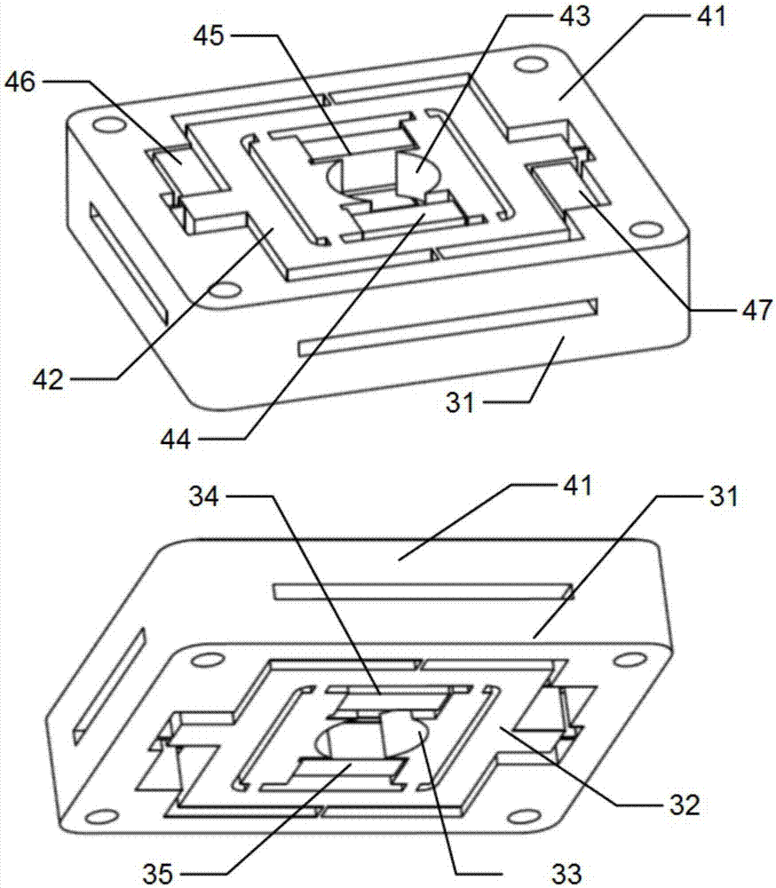
[0023] Such as Figure 4 As shown, the lower drive structure 3 and the upper drive structure 4 can drive the output sha...


PUM


Abstract

The invention provides a clamp-driven integrated type piezoelectric-drive high-precision rotary actuator and method thereof. The actuator comprises an actuator pedestal, a lower thrust ball bearing being installed at the pedestal and being capable of bearing an axial load, a lower drive structure arranged above the pedestal, an upper drive structure connected with the lower drive structure 3 into one, an output shaft being capable of being clamped and limited by the lower drive structure and the upper drive structure after installation, an upper thrust ball bearing installed above the output shaft, and a top cover installed above the thrust ball bearing. In addition, the invention also discloses an actuating method for the actuator. Piezoelectric ceramic units are driven according to a certain order to realize bidirectional large-angle rotation driving. The upper drive structure and the lower drive structure have completely identical geometric dimensions; and with slow feeding, one-time processing moulding is realized, the processing and assembling flow is simplified, and the implementation is high. Moreover, the actuator employs the piezoelectric ceramic units as driving elements. The actuator has characteristics of large output stroke, high output resolution, and power-off self-locking.

Description

Technical field [0001] The invention relates to a stepping type rotary actuating device driven by piezoelectricity, in particular to a piezoelectric driving high-precision rotary actuating device which is convenient for processing and implementation and is integrated with clamp driving and its realization method. Background technique [0002] In recent years, piezoelectric actuators have continued to develop, supporting the development and construction of important industries such as national defense, aerospace, and machinery manufacturing. A wide variety of piezoelectric actuators have also been derived. However, due to the shortcomings of piezoelectric materials with small strokes, On the one hand, it is difficult for piezoelectric ceramic actuators to achieve large strokes, especially large angular displacement output, on the other hand, it also puts forward higher requirements for processing and assembly. Therefore, there is an urgent need for a stepping rotary actuator with ...

Claims


Application Information

Patent Timeline
Patent Type & Authority Applications(China)
IPC IPC(8): H02N2/04
CPCH02N2/046
Inventor 宋思扬徐明龙邵恕宝张舒文
Owner 西安朗威科技有限公司
Why Eureka
Try Eureka