
Metal cutting machine

A cutting machine and metal technology, applied in the direction of metal processing equipment, grinding machine parts, grinding feed movement, etc., can solve the problems of danger, poor cutting environment, etc., to prevent danger, save manpower, and improve work efficiency Effect

Inactive Publication Date: 2017-06-27
TIANJIN CARMEL TECH DEV CO LTD
View PDF0 Cites 3 Cited by
  • Summary
  • Abstract
  • Description
  • Claims
  • Application Information

AI Technical Summary

Problems solved by technology

[0002] With the development of society, the application of metal pipes is becoming more and more extensive. Some metal pipes need to be cut before they can be used. This requires cutting. The traditional cutting method is done by manual operation, which often causes danger. , and in such a cutting environment is also very poor, therefore, it is very necessary to design a set of fully automatic metal cutting device

Method used


Image

  • Metal cutting machine

Examples


Embodiment Construction

[0013] In order to make the object, technical solution and advantages of the present invention clearer, the present invention will be further described in detail below in conjunction with the accompanying drawings and embodiments. It should be understood that the specific embodiments described here are only used to explain the present invention, not to limit the present invention.

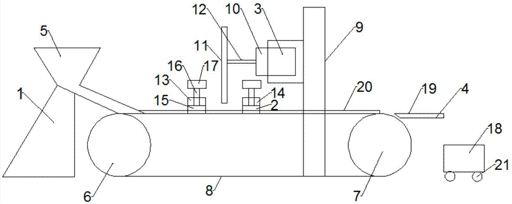
[0014] Such as figure 1 As shown, a metal cutting machine includes a feeding device 1, a fixed clamping device 2, a cutting device 3 and a receiving device 4, and the feeding device 1 includes a feeding hopper 5, a driving wheel 6 and a driven wheel 7, and the The driving wheel 6 and the driven wheel 7 are connected by a transmission belt 8, the feed hopper 5 is located at one end of the transmission belt 8, the cutting device 3 includes a frame 9, a drive motor 10 and a grinding wheel 11, and the grinding wheel 11 passes through a rotating shaft 12 is fixedly installed on the drive motor 10, the ...


PUM


Abstract

The invention relates to the field of metal material processing equipment, in particular to a metal cutting machine, comprising a feeding device, a fixed clamping device, a cutting device and a receiving device, the feeding device includes a feeding hopper, a driving wheel and a driven wheel, and a driving wheel and a driven wheel The moving wheels are connected by a conveyor belt, and the feed hopper is located at one end of the conveyor belt. The invention realizes the fully automatic metal cutting design by including the feeding device, the fixed clamping device, the cutting device and the receiving device, and does not require excessive manual operations, and only needs to put the metal pipe to be cut into the feeding hopper. However, the work efficiency is greatly improved, the manpower is saved, and the danger brought by the traditional manual operation is prevented. It is easy to use and popularize.

Description

technical field [0001] The invention relates to the field of metal material processing, in particular to a metal cutting machine. Background technique [0002] With the development of society, the application of metal pipes is becoming more and more extensive. Some metal pipes need to be cut before they can be used. This requires cutting. The traditional cutting method is done by manual operation, which often causes danger. , and it is also very poor in such a cutting environment, therefore, it is very necessary to design a fully automatic metal cutting device. Contents of the invention [0003] In view of the above problems, the present invention provides a metal cutting machine. The present invention realizes the fully automatic design of metal cutting by including a feeding device, a fixed clamping device, a cutting device and a receiving device, and does not require excessive manual operations. It only needs to put the metal pipe to be cut into the feeding hopper, whi...

Claims


Application Information

Patent Timeline
Patent Type & Authority Applications(China)
IPC IPC(8): B24B27/06B24B41/00
CPCB24B27/06B24B41/005
Inventor 杨晓曼赵玥起张俊兰
Owner TIANJIN CARMEL TECH DEV CO LTD
Learn More