Printed circuit board computer board making system

A technology for printed circuit boards and red copper plates, applied in the system field, can solve the problems of expensive printing equipment, and achieve the effects of convenient design, improved plate-making accuracy, and reduced costs

Inactive Publication Date: 2004-07-21
天津市阿波罗信息技术有限公司
View PDF0 Cites 8 Cited by
  • Summary
  • Abstract
  • Description
  • Claims
  • Application Information

AI Technical Summary

Problems solved by technology

Among them, because the printing equipment is relatively expensive, it cannot be afforded by ordinary design companies, so it must be made by the corresponding plate-making company

Method used


Image

  • Printed circuit board computer board making system
  • Printed circuit board computer board making system
  • Printed circuit board computer board making system

Examples


Embodiment 1

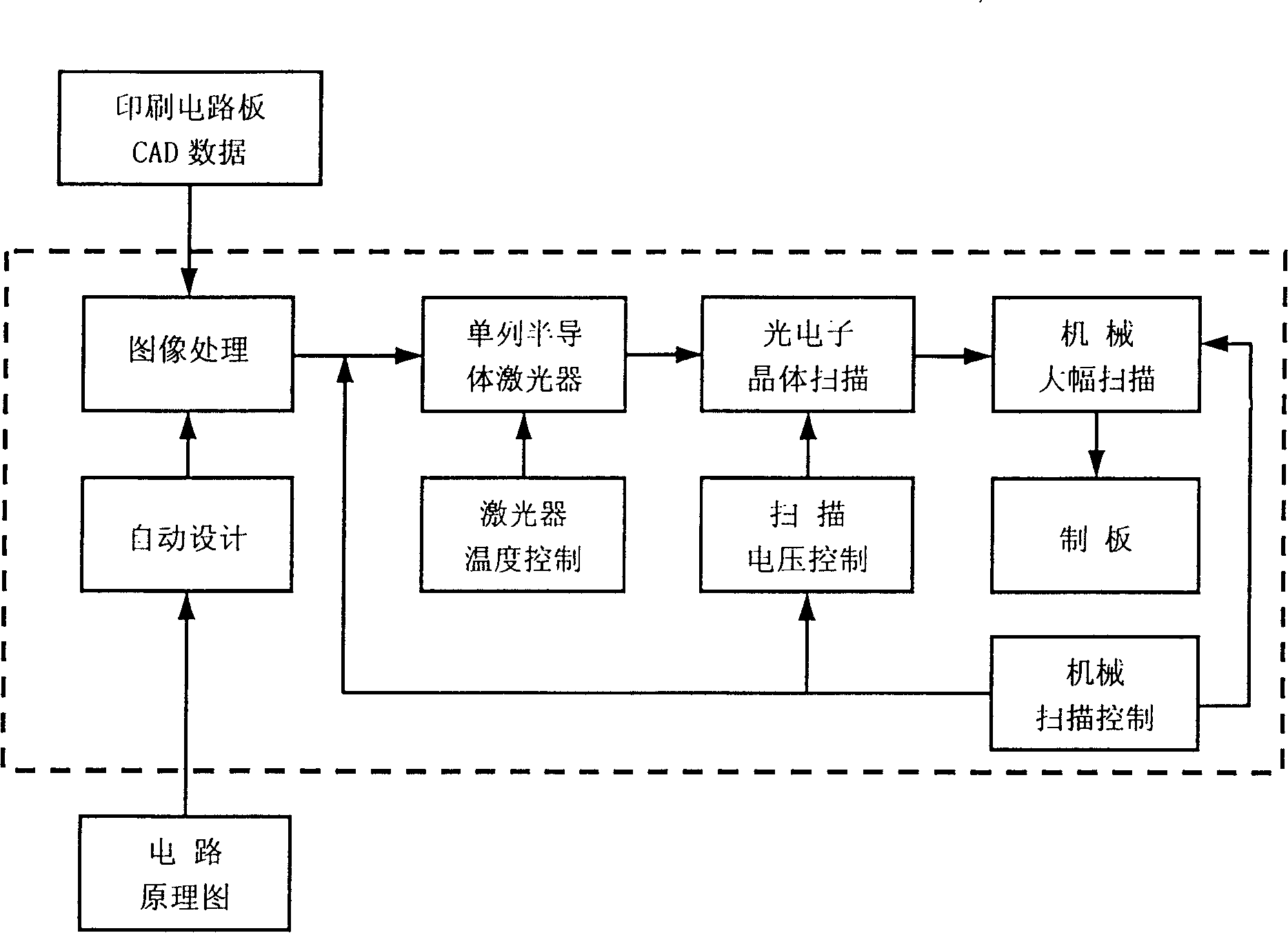
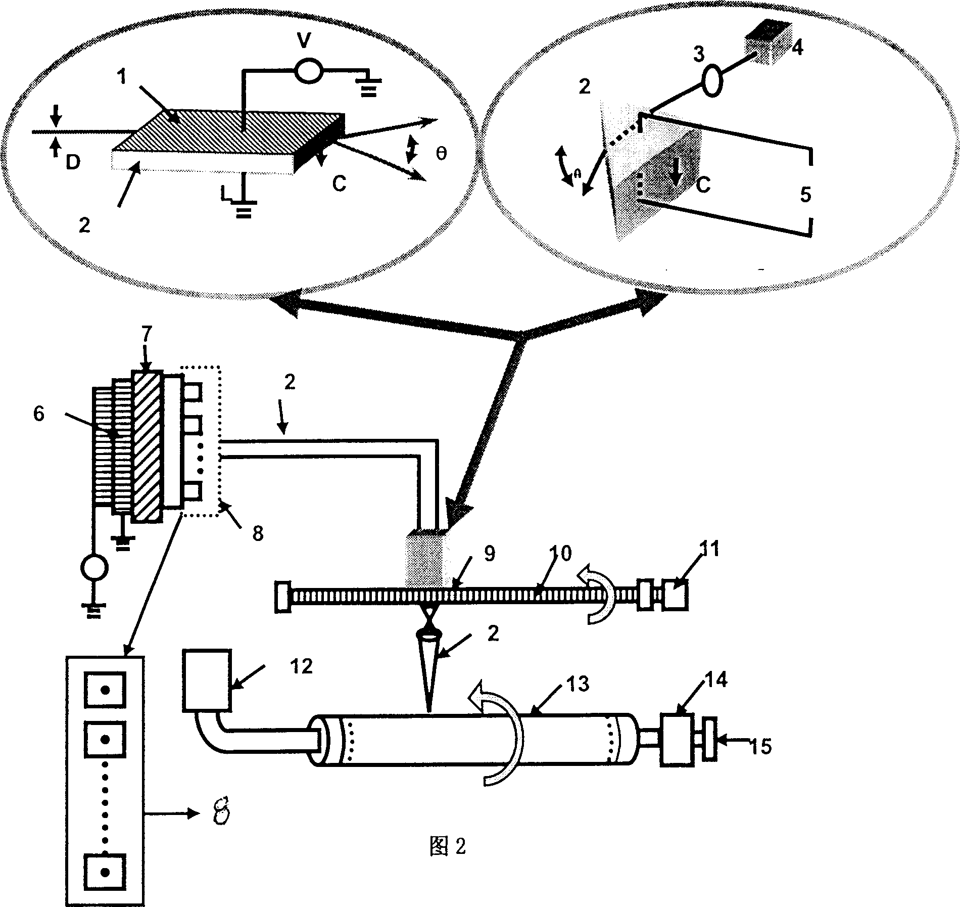
[0037] Implementation 1: Printed circuit board CTP plate making system, using laser solid-state micro-scanning technology to replace the current laser 4 array mechanical scanning; fixing the semiconductor device on the copper plate 7, and installing several silicon temperature control devices 6 through the back of the copper plate; and on the drum Long holes are punched in the middle of 23, and many small holes are punched on the surface; the laser thermal plate material is made by the method of heat-sensitive pigments, and the plate is made directly by a computer printer. The small holes on the surface of the drum achieve the function of constant temperature control and plate fixation;

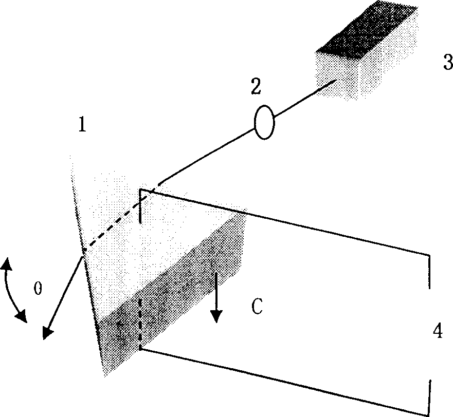
[0038] The laser solid-state micro-scanning technology actually uses such as image 3 , 4 The electrical optical deflector shown. When the laser 4 irradiates the electro-optical crystal 2 through the lens 3, it becomes incident light. The emitted light of the electro-optical crystal generates a d...


PUM


Abstract

A computerized plate-making system for printed circuit board (PCB) features that a laser solid scanning technique is substituted for existing laser-array mechanical scanning, the semiconductor device is fixed to the red copper board with several temp-controlling silicon devices on its back, the drum has a central long hole and many small holes on its surface, and the laser thermosensitive plate is made of thermosensitive pigments. Its advantages are high precision and speed, and low cost.

Description

Technical field [0001] The present invention is a system related to the field of image plate making. Background technique [0002] The computer to plate system is a revolutionary technological advancement in the current image platemaking field. Its appearance eliminated the traditional craftsmanship of laser phototypesetting and photographic plate making. Its characteristic is to realize full digital plate making, which can improve plate making accuracy, save construction period, realize integrated production method of design plate making, reduce cost and reduce pollution. In 1995, we could see products made by several manufacturers, but there were still many problems in technology and practical application when direct plate making, and the price was very expensive. After 1998, computer systems have made breakthroughs in quality, and their prices have dropped. Because of their unique performance, computer technology has received widespread attention and a certain range of applica...

Claims


Application Information

Patent Timeline
Patent Type & Authority Applications(China)
IPC IPC(8): B41C1/05
Inventor 顾泽苍
Owner 天津市阿波罗信息技术有限公司
Why Eureka
Try Eureka