A liquid crystal photomask, its application and plate making device

A photomask and liquid crystal technology, which is used in photoplate-making process exposure devices, optics, nonlinear optics, etc., can solve the problems of large deviation between accuracy and design accuracy, easy to be affected by temperature, and difficult to debug line width. The effect of improving the accuracy of plate making and reducing the number of image transfers

Active Publication Date: 2017-01-04
十二秒融媒体(山东)有限公司
View PDF7 Cites 0 Cited by
  • Summary
  • Abstract
  • Description
  • Claims
  • Application Information

AI Technical Summary

Problems solved by technology

[0009] According to the above existing technologies, it can be known that using liquid crystal panels as masks has many advantages. However, according to the existing technologies, when it is applied to actual production, there is often a large deviation between the accuracy and the design accuracy, and it is difficult to debug the line width. Inaccurate accuracy, susceptible to temperature effects, long-term processing creep and other technical problems

Method used


Image

  • A liquid crystal photomask, its application and plate making device
  • A liquid crystal photomask, its application and plate making device
  • A liquid crystal photomask, its application and plate making device

Examples


Embodiment 1

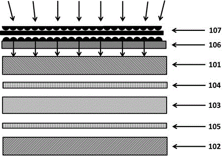
[0029] see figure 1 , the specific embodiment 1 provides a liquid crystal photomask, characterized in that the photomask includes an imaging controller (not shown), a light guide layer 106, a first optical deflector 101, a liquid crystal layer 103 and the second optical deflector 102; the liquid crystal layer 102 is sandwiched between the first optical deflector 101 and the second optical deflector 102; the liquid crystal layer 103 is a twisted nematic liquid crystal layer. A first transparent electrode layer 104 is provided on the surface of the first optical deflector 101 in contact with the liquid crystal layer 103 ; a second transparent conductive layer 105 is provided on the surface of the second optical deflector 102 in contact with the liquid crystal layer 103 .

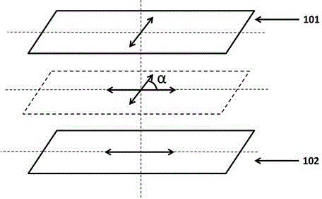
[0030] see figure 2 , the angle between the polarization direction of the first optical deflector 101 and the second optical deflector 102 is 90 degrees; the light guide layer 106 is arranged on the light in...

Embodiment 2

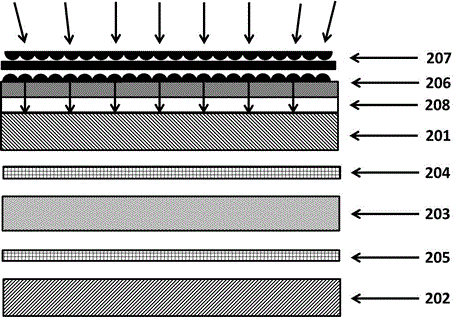
[0036] see image 3 , this specific embodiment 2 provides a kind of liquid crystal photomask, it is characterized in that, described photomask comprises, imaging controller, light guide layer 206, first optical deflection film 201, liquid crystal layer 203 and second optical deflection sheet 202; the liquid crystal layer 203 is sandwiched between the first optical deflection film 201 and the second optical deflection film 202; the liquid crystal layer 203 is a twisted nematic liquid crystal layer. A first transparent electrode layer 204 is arranged on the surface of the first optical deflector 201 in contact with the liquid crystal layer 203; a second transparent conductive layer 205 is arranged on the surface of the second optical deflector 202 in contact with the liquid crystal layer 203; The included angle between the polarization direction of the optical deflector 201 and the second optical deflector 202 is 90 degrees (same as in embodiment 1, not shown in the figure); si...

Embodiment 3

[0040] see Figure 4 , this specific embodiment 2 provides a kind of liquid crystal photomask, it is characterized in that, described photomask comprises, imaging controller, light guide, 206, first optical deflection film 301, liquid crystal layer 303 and second optical deflection sheet 302; the liquid crystal layer 303 is sandwiched between the first optical deflection film 301 and the second optical deflection film 302; the liquid crystal layer 303 is a twisted nematic liquid crystal layer. A first transparent electrode layer 304 is arranged on the surface of the first optical deflector 301 in contact with the liquid crystal layer 303; a second transparent conductive layer 305 is arranged on the surface of the second optical deflector 302 in contact with the liquid crystal layer 303; The angle between the polarization direction of the optical deflector 301 and the second optical deflector 302 is 90 degrees; the light guide layer 306 is arranged on the light incident side of...


PUM


Abstract

A liquid crystal photomask, its application and a plate making device. The photomask includes an imaging controller, a light guide layer, a first optical deflector, a liquid crystal layer and a second optical deflector; the liquid crystal layer is sandwiched between the first optical deflector and the second optical deflector; A first transparent electrode layer is arranged on the surface of the first optical deflection plate in contact with the liquid crystal layer; a second transparent conductive layer is provided on the surface of the second optical deflection plate in contact with the liquid crystal layer; the first optical deflection plate and the second The included angle of the polarization directions of the optical deflector is 90 degrees; the light guide layer is arranged on the light incident side of the first optical deflector. The invention provides a liquid crystal photomask that realizes multi-mask overprinting without changing masks, has high precision, can be adjusted, has good stability and can work for a long time, and is used in plate making to replace film.

Description

technical field [0001] The invention relates to a photomask and relates to a wide range of printing fields, in particular to a liquid crystal photomask, its application and a plate-making device. Background technique [0002] In a wide range of printing fields, including commonly referred to as printing plate printing, circuit printing, photolithography and other fields, photomasks are an important part of them. With the development of laser plate making, electron beam direct writing and other technologies, the research focus has gradually shifted to the field of direct plate making. In contrast, the research on plate making printing or exposure imaging relying on masks is relatively lagging behind. However, in terms of market share In terms of wide application and wide application, mask printing is still the top priority of related industries. Therefore, solving the related problems in traditional plate making is the key to cracking the decline of the industry and striving ...

Claims


Application Information

Patent Timeline
Patent Type & Authority Patents(China)
IPC IPC(8): G02F1/1333G02F1/1335G02F1/13357G03F7/20
Inventor 杨涛
Owner 十二秒融媒体(山东)有限公司
Why Eureka
Try Eureka