
Positioning structure of mounting hole of laminated tempered glass and processing method thereof

A tempered glass and positioning structure technology, applied in chemical instruments and methods, lamination devices, lamination, etc., can solve problems such as glass bursting, upper and lower mounting holes are not vertical and coaxial, and unilateral force, so as to facilitate later installation , Improving the effect of using quality and safety

Active Publication Date: 2017-06-27
XIANGSHI ENERGY SAVING GLASS KUNSHAN CO LTD
View PDF6 Cites 2 Cited by
  • Summary
  • Abstract
  • Description
  • Claims
  • Application Information

AI Technical Summary

Problems solved by technology

Limited by the accuracy of flat glass cold processing equipment, when the pre-designed and processed holes of the upper and lower glass are superimposed with lamination, it is easy to cause the upper and lower mounting holes to be not vertical and coaxial, which will bring a lot of trouble to the subsequent installation of hardware fasteners and easily cause Unilateral force, severe uneven force can cause the glass at the hole to burst, affecting product quality and life safety

Method used


Image

  • Positioning structure of mounting hole of laminated tempered glass and processing method thereof
  • Positioning structure of mounting hole of laminated tempered glass and processing method thereof

Examples


Embodiment Construction

[0018] Below in conjunction with specific embodiment, further illustrate the present invention. It should be understood that these examples are only used to illustrate the present invention and are not intended to limit the scope of the present invention. In addition, it should be understood that after reading the teachings of the present invention, those skilled in the art can make various changes or modifications to the present invention, and these equivalent forms also fall within the scope defined by the appended claims of the present application.

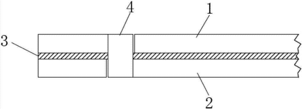
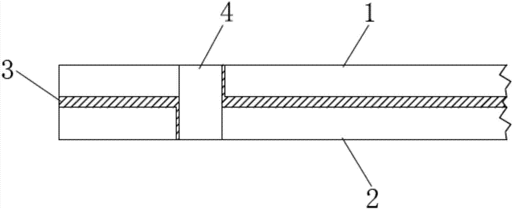
[0019] like figure 1 and figure 2 A laminated tempered glass installation hole positioning structure shown includes a first tempered glass 1 , a second tempered glass 2 and a laminated glass 3 .

[0020] The first tempered glass 1 and the second tempered glass 2 are provided with mounting holes at corresponding positions, the first tempered glass 1 and the second tempered glass 2 are stacked up and down so that the mounting ...


PUM

PropertyMeasurementUnit
thicknessaaaaaaaaaa

Abstract

The invention relates to a positioning structure of a mounting hole of laminated tempered glass and a processing method thereof. First tempered glass and second tempered glass are overlaid up and down, a plastic clip is arranged between the first tempered glass and the second tempered glass, a positioning ring is sleeved in corresponding mounting holes up and down, the shape of the positioning ring is matched with the shape of the mounting hole, an error gap exists between the hole wall of the first tempered glass and that of the second tempered glass, and the error gap is extruded outward in a high-temperature and high-pressure condition through laminated glue to a considerable volume dose to fill and press and fix the positioning ring in the mounting holes. The processing method comprises the following steps of: grinding an edge, chamfering the edge and setting the dimension; processing the mounting holes; tempering an original glass sheet; overlying the first tempered glass and the second tempered glass up and down, arranging laminated glue, and sleeving the position ring to fill the error gap and compress the positioning ring through a tempered glass glue laminating process. The positioning structure avoids a mounting trouble that upper and lower glass mounting holes are not absolutely vertical and coaxial, and the service quality and the safety of the product are improved.

Description

technical field [0001] The invention belongs to the technical field of interlayer tempered glass mounting hole positioning, and in particular relates to a laminated tempered glass mounting hole positioning structure and a processing method thereof. Background technique [0002] After tempering, the glass cannot be cold-processed, and the required mounting holes must be processed before tempering can be performed, and then the lamination process of the upper and lower glass is carried out. Limited by the accuracy of flat glass cold processing equipment, when the pre-designed and processed holes of the upper and lower glass are superimposed with lamination, it is easy to cause the upper and lower mounting holes to be not vertical and coaxial, which will bring a lot of trouble to the subsequent installation of hardware fasteners and easily cause Unilateral force, severe uneven force can cause the glass at the hole to burst, affecting product quality and life safety. Contents ...

Claims


Application Information

Patent Timeline
Patent Type & Authority Applications(China)
IPC IPC(8): B32B38/04B32B38/00B32B37/06B32B37/10
CPCB32B37/06B32B37/10B32B38/04B32B38/1841
Inventor 韩伟军
Owner XIANGSHI ENERGY SAVING GLASS KUNSHAN CO LTD
Learn More