A multifunctional shield with guide slots

一种导向槽、多功能的技术,应用在防御物等方向,能够解决抛掷液体飞溅、能力不足、伤害等问题,达到提高安全保障、全面防护、避免伤害的效果

Active Publication Date: 2019-04-26
BENGBU ZHIDA TECH CONSULTING CO LTD
View PDF5 Cites 2 Cited by
  • Summary
  • Abstract
  • Description
  • Claims
  • Application Information

AI Technical Summary

Problems solved by technology

In the face of such attacks, the shields of the prior art used by law enforcers can generally resist the direct damage of the throwing liquid to the shield holder, but since the surface of the shield is a plane or arc surface, the throwing liquid will splash irregularly on the shield surface , the direction-changing throwing liquid can easily cause damage to other coordinated law enforcement personnel
[0008] In addition, the shields of the prior art also appear to have insufficient ability when attacking criminals as weapons. Most of them are pure protective equipment, and it is urgent to enhance their attack capabilities to achieve both offensive and defensive effects.

Method used


Image

  • A multifunctional shield with guide slots
  • A multifunctional shield with guide slots
  • A multifunctional shield with guide slots

Examples


Embodiment 1

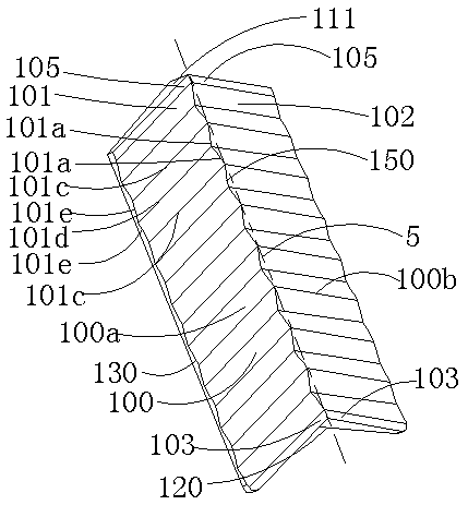
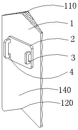
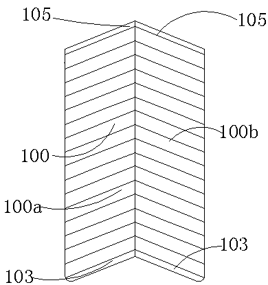
[0036] Embodiment 1: as Figure 1-5 As shown, a multifunctional shield with a guide groove includes a shield body 1, a handle 4, a pad 2 and an elbow locking fixture 3, and the shield body 1 includes a shield body front 100 and a shield body back 140, The pad 2 is connected to the back 140 of the shield body, the handle 4 and the elbow locking fixture 3 are connected to the shield body 1 through the pad 2, and the transverse cross-sectional shape of the front 100 of the shield body is It is an outer convex surface, and the outer convex surface may be an inverted V-shaped surface or an arc surface, or may be an outer convex trapezoid or other outer convex shapes. The convex surface can effectively unload the attack power and protect the shield holder when under attack.

[0037] like Figure 1-5As shown, the front of the shield body is provided with a left guide groove group 100a and a right guide groove group 100b, the left guide groove group 100a is composed of a plurality o...

Embodiment 2

[0045] Embodiment 2: as Figure 7 as shown, Figure 7 Numeral labels for geometric structures in figure 1 The corresponding numerals in are the same, indicating that the structure of the same numerals in Example 2 and Example 1 is basically the same. A multifunctional shield with a guide groove, comprising a shield body 1, a handle 4, a pad 2 and an elbow locking fixture 3, the shield body 1 includes a shield body front 100 and a shield body back 140, the shield body The pad 2 is connected to the back 140 of the shield body, the handle 4 and the elbow locking fixture 3 pass through the pad 2 and connected to the shield body 1, and the front 100 of the shield body has a transverse cross-sectional shape that is convex. , the convex surface can be an inverted V-shaped surface or a circular arc surface, and can also be a convex trapezoid or other convex shapes. In addition, the convex surface can effectively unload the attack power and protect the shield holder when under attac...


PUM


Abstract

A multifunctional shield with guide grooves, relating to the field of police shields, comprising a shield body, a handle, a pad and an elbow locking fixture, the shield body includes a shield body front and a shield body back, the pad It is connected to the back of the shield body, the handle and the elbow locking fixture are connected to the shield body through the pad, the front of the shield body is convex, and the front of the shield body is provided with a left guide groove group and the right guide groove group, the left guide groove group is composed of a plurality of left guide grooves, the right guide groove group is composed of a plurality of right guide grooves, and the shield body also includes a longitudinal axis, so The left guide groove extends from the longitudinal axis to the left edge of the front of the shield body along the inclined downward direction of the outer convex surface, and the left guide groove group and the right guide groove group are arranged symmetrically along the longitudinal axis, The shield includes unloading mode and rebound attack mode when used.

Description

technical field [0001] The invention relates to a shield, in particular to a multifunctional police shield with guide grooves. Background technique [0002] Shields are an ancient defensive weapon. Soldiers holding shields can effectively block the enemy's weapons and protect their own lives. In ancient combat, whether in the history of China, ancient Greece or ancient Rome, the shield is a very important weapon for tactical use and has been developed to this day. Although the glory of the shield in military use no longer exists today, the shield has a new life in the field of modern police use. In the current atmosphere where the world pattern tends to be peaceful, large-scale wars are unlikely to occur, but individual criminal activities within the country frequently occur. Therefore, the personal safety issues faced by police officers are the first to bear the brunt. At this time, police shields It has played a very important role in the field of single police protectio...

Claims


Application Information

Patent Timeline
Patent Type & Authority Patents(China)
IPC IPC(8): F41H5/08
CPCF41H5/08
Inventor 曾国庆
Owner BENGBU ZHIDA TECH CONSULTING CO LTD
Why Eureka
Try Eureka