Shield with U-shaped protective device

A protective device and shield technology, applied in the direction of defensive objects, can solve the problems of throwing liquid splash, lack of ability, damage, etc., and achieve the effects of avoiding damage, increasing sliding distance, and good attack performance

Inactive Publication Date: 2018-12-28
临沂高新自来水有限公司
View PDF6 Cites 0 Cited by
  • Summary
  • Abstract
  • Description
  • Claims
  • Application Information

AI Technical Summary

Problems solved by technology

In the face of such attacks, the shields of the prior art used by law enforcers can generally resist the direct damage of the throwing liquid to the shield holder, but since the surface of the shield is a plane or arc surface, the throwing liquid will splash irregularly on the shield surface , changing directions, throwing liquids can easily cause harm to other law enforcement officers in coordination
[0009] In addition, the shields of the prior art also appear to have insufficient ability when attacking criminals as weapons. Most of them are pure protective equipment, and it is urgent to enhance their attack capabilities to achieve both offensive and defensive effects.

Method used


Image

  • Shield with U-shaped protective device
  • Shield with U-shaped protective device
  • Shield with U-shaped protective device

Examples


Embodiment 1

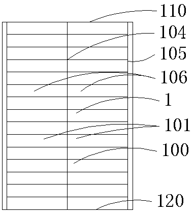
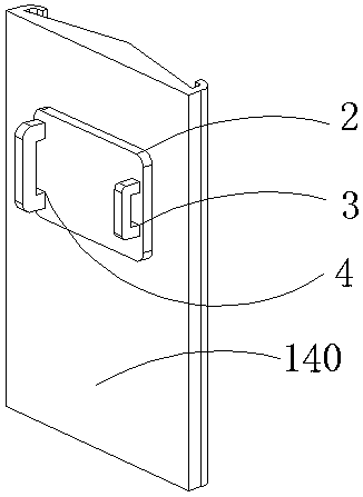
[0040] Embodiment 1: as Figure 1-3 As shown, a shield with a U-shaped protective device includes a shield body 1, a handle 4, a pad 2 and an elbow locking fixture 3, and the shield body 1 includes a shield body front 100 and a shield body back 140, The pad 2 is connected to the back side 140 of the shield body, the handle 4 and the elbow locking fixture 3 pass through the pad 2 and are connected to the shield body 1, and the front side of the shield body 100 includes a vertex in a transverse section. and two side points, the vertex forms the vertex intersection line 104, the side point forms the side point intersection line 105, and the height of the vertex intersection line 105 gradually decreases and extends to the side point intersection line 110 to form the side 106, and the shield body The front side 100 is axially symmetrical along the vertex intersection line 104, and the front side 100 of the shield body is an outer convex arc surface, an inverted V-shaped surface or ...

Embodiment 2

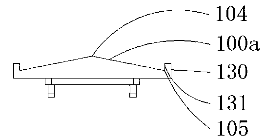
[0052] Such as Figure 8-11 As shown, this embodiment is an improvement on the protective device 130 based on the first embodiment, and the protective device 130 also includes a second bending edge 132, a first bending edge 131 and a second bending edge And the side 100a forms a U-shaped guard. Further, a barb is provided at the top of the second bending edge, that is, a barb 133 is provided on the U-shaped guard.

[0053] Capturing mode: Specifically, the shield holder sets the guide groove 101 of the shield to face the projectile at a certain angle of inclination according to the trajectory of the projectile. Now take the projectile sliding along the first trajectory 150a as an example, and the projectile moves along the The first moving track 150 slides and collides with the first bent edge 131 of the protective device 130 on the front of the shield body. Since the protective device 130 also includes a second bent edge 132, the first bent edge 131, the second bent edge an...

Embodiment 3

[0056] Such as Figure 7 As shown, this embodiment is an improvement on the shield body 1 on the basis of the first embodiment. The shield body 1 also includes a shield head 110 and a shield tail 120, both of which are inverted V-shaped. Preferably, the inverted V-shaped bottom of the shield tail 120 is provided with a concave semicircular edge 122 . The shield body front 100 also includes a shield tail transition surface 103 and a shield head transition surface 102, the folds formed by the guide grooves 101 extend toward the shield head 110 and intersect with the shield head transition surface 102, the folds formed by the guide grooves 101 Extending toward the shield tail 120 and intersecting with the shield tail transition surface 102 . Providing a transition surface between the shield head 110 and the shield tail 120 and the wrinkled surface can enhance the strength of the shield head 110 and the shield tail 120 and reduce manufacturing difficulty. The inverted V-shaped ...


PUM


Abstract

The invention discloses a shield with a U-shaped protective device, including a shield body, a hand-held handle, a pad and an elbow-fixing device. The shield body comprises a front surface and a backsurface, and the pad is connected to the back surface. The hand-held handle and the elbow-fixing device are connected to the shield body through the pad. The front surface of the shield body is provided with a protective device, and the protective device is arranged along the side line to the front of the shield. The protective device includes the first bending edge and the second bending edge. The first bending edge, the second bending edge and the side edge form the U-shaped protective device. A barb is on top of the second bending edge. The shield body also includes a shield head and a shield tail, and both the head and the tail are inverted V-shaped. The inverted V-shaped bottom of the shield tail is provided with a concave semi-circular edge.

Description

[0001] This application is a divisional application of an invention patent application titled: A shield with a guiding protection function, the application date is: March 5, 2017, and the application number is: 201710125745.4. technical field [0002] The invention relates to a shield, in particular to a police shield with guiding protection function. Background technique [0003] Shields are an ancient defensive weapon. Soldiers holding shields can effectively block the enemy's weapons and protect their own lives. In ancient combat, whether in the history of China, ancient Greece or ancient Rome, the shield is a very important weapon for tactical use and has been developed to this day. Although the glory of the shield in military use no longer exists today, the shield has a new life in the field of modern police use. In the current atmosphere where the world pattern tends to be peaceful, large-scale wars are unlikely to occur, but individual criminal activities within th...

Claims


Application Information

Patent Timeline
Patent Type & Authority Applications(China)
IPC IPC(8): F41H5/08
CPCF41H5/08
Inventor 曾国庆
Owner 临沂高新自来水有限公司
Why Eureka
Try Eureka